


A mathematical model for the three-dimensional simulation of free dendritic growth and microstructure evolution was developed based on the growth mechanism of crystal grains and basic transfer equations such as heat, mass and momentum transfer equations. Many factors including constitutional undercooling, curvature undercooling and anisotropy, which had vital influences on the microstructure evolution, were considered in the model. Simulated results showed that final microstructural patterns and free dendritic growth could be predicted reasonably and calculated results were coincident with experimental. The simulated results of free dendritic growth indicated that the strength of anisotropy has significant effects on free dendritic growth, dendrite profile, micro solute and temperature distribution. The dendritic grain profiles with fully-grown parallel secondary arm tend to be formed at the intensive anisotropy, while near octahedral grain profiles with small protuberances of surface at low strength of anisotropy. The simulated results of free dendritic growth also indicated that there are small molten pools left in interdendritic areas. This is helpful to understand the fundamental of the formation of microstructure related defects such as microsegregation and microporosity.
Key words : Modeling and simulation. Dendritic grain growth, Microstructure evolution
Solidification microstructure in cast alloys is one of most observed areas in the materials science and engineering. Mechanical propertics of castings are influenced mostly by final microstructure patterns [1] . Dendritic growth is perhaps the most obscrved phenomenon in solidification of cast alloys. It is essential to make a fundamental understanding of dendritic growth and find the effective methods of microstructure control in order to obtain satisfied mechanical properties and service performancc. In the last decades, to study the evolution of solidification microstrueture most experimental techniques were developed by inspecting the nucleation and dendritic growth in transparent materials [2,3] . Nevertheless, The principle of free dendrite growth and microstructure evolution involves to different domains such as crystallography, thermodynamics, transport phenomena and micromechanics. Low efficiency and high cost of experiment prevents us from understanding the mechanism of microstructure evolution further. Numerical simulation, however, can extend our comprehension of microstructure formation and predict dendrite morphology, microstructure features, solid/liquid interface and microstructure related defects such as microsegregation and microporosity.
A few numerical models were developed for the simulation of dendrite growth in the last decades. They include deterministic techniques such as phase field method or spline mathematics approaches for simulation of dendrite morphology and microscgregation patterns, solidification kinetics deterministic models for calculating the evolution of solid and dendritic grain size, and probabilistic approaches such as Monte Carlo and Cellular Automaton techniques for simulating the evolution of dendritic morphologies [4-8] .
The objective of the paper is to present a physical and numerical model for three-dimensional simulation of microstructure and microsegregation based on the nucleation and growth of crystal grains and basic transfer equations such as heat transfer, mass transfer and momentum transfer. The model trics to consider more factors, which have vital influence on the cvolution of microstructure and microsegregation, such as constitutional undcrcooling, curvature undercooling and anisotropy. Then simulation results of some cases were discussed in dctail.
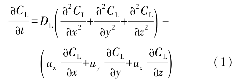
It is essential to establish a rational physical and mathematical model before computing and simulating the solidification microstructure and solute redistribution process. Although many mathematical models had been presented [9,10] , most of them were only applicable to the two dimensional simulation. Recent work by the author has focused on the establishment of a three-dimensional mathe-matical model of microstructure cvolution and free dendrite growth. The solidification process of binary alloys is governed by the evolution of the temperature field T ( x , y , z , t ) , concentration field C ( x , y , z , t ) , velocity field u x ( x , y , z , t ) , u y ( x , y , z , t ) , u z ( x , y , z , t ) and solid fraction f S ( x , y , z , t ). Most of governing equations have uniformed mathematical representation no matter where unit domain locates, in solid phase, or in liquid phase, or at the solid/liquid interface. The boundary conditions must be satisfied well at the moving solid/liquid interface and on the edge of cast domain. Besides the typical mass, heat and momentum transfer equations, equations that describe the physics of the solidification process are as follows.
Liquid species conservation equation:
Solid species conservation equation:

Local equilibrium at the solid/liquid interface:

Solute conservation at the solid/liquid interface:

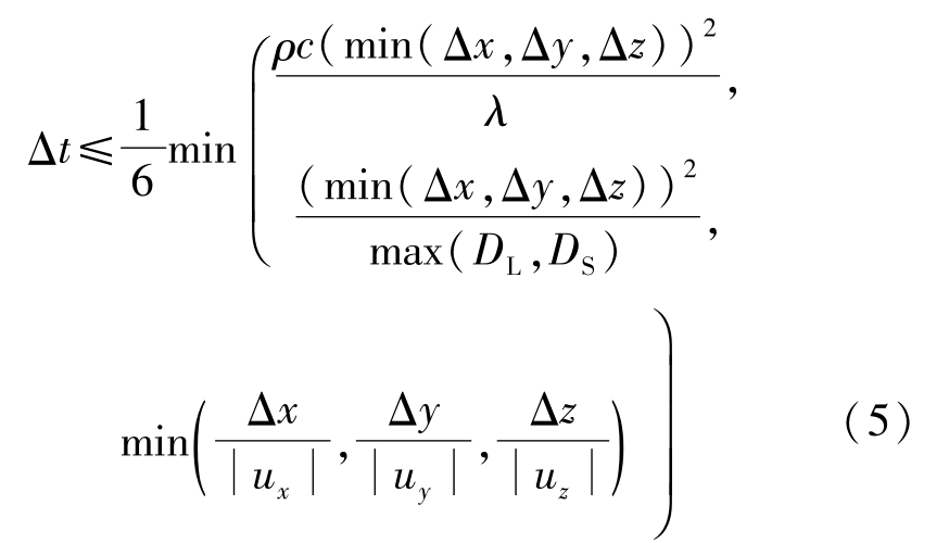
The solidification process is governed by Eqs.(1)~(7).An explicit finite difference scheme is used for calculation of temperature and concentration field both in solid and liquid phases as well as velocity field in liquid phase. The difference scheme is stable when the following equation used to calculate the time step is satisfied:
The nucleation models of equiaxed grains, which are based on the heterogeneous nucleation theory, can be classified as two groups:the instantaneous nucleation model and the continuous nucleation model. The former assumes that all nuclei are generated at the nucleation temperature T N .The latter, however, assumes a continuous dependency of N on temperature. Mathematical relationship is provided to correlate the nucleation velocity with undercooling, cooling rate and temperature. Another model, referred to as the dynamic nucleation, has been developed to consider the effect of melt convection on the breaking of dendritic arms and migration of nuclei. The continuous nucleation model used in the paper to calculate the nucleation velocity assumes that the grain density grows continuously with the increasing undercooling. The relationship between the nucleation velocity and the undercooling obeys Gaussian distribution and is given by

where the maximum density of grains n max that can form in the melt was set to 4.7×10 10 m -3 .The standard deviation of the distribution Δ T σ ranges from 0.5K to 2.0K. The centre of the distribution Δ T N is the mean nu cleation undercooling. It was set to 2.5K for all cases.
The probability model of dendrite growth is based on the principle of minimum free energy. Capture probability of the neighboring liquid cells by a nucleus can be given by

where total free energy change Δ G is

the undercooling of liquid in Eq.(11)can be calculated by

only at very high solidification velocity the effect of kinetic undercooling Δ T k is needed to calculate, so it is not taken into account in the model. In Eq.(12),other terms in the right hand side can be expressed respectively as

where f ( θ i ) is the anisotropy function given by

where θ i is the angle between the interfacial normal vector and the positive direction of x -, y -or z -axis. It is calculated by

The program code was written in C language. The medium and final values of T , C and f S were stored to the same data file and shown in three-dimensional plots. Some parameters used in the simulation are listed in Table 1.
The relation between the nucleation rate and the undercooling is shown in Fig. 1.With the increase of undercooling, nucleation rate of grains obeys Gaussian distribution.
When the maximum density of grains n max is set aconstant, the undercooling starting to nucleate goes up and yet the undercooling finishing the nucleation goes down with the reduction of the standard deviation of the distribution Δ T σ . Therefore, the undercooling range of nucleation becomes much narrower and the maximum nucleation rate rises gradually. As a result, most of nuclei are formed nearly at the same time, which contributes to the uniformity of grain size and refinement of grains. So it is an effective measure to control the final grain size by decreasing the standard deviation of the distribution during the solidification.
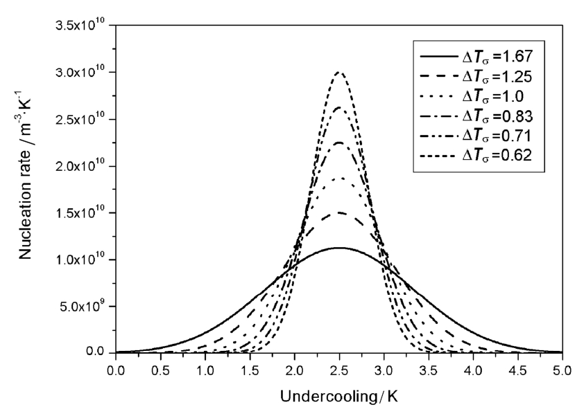
Fig. 1 Relations between undercooling and nucleation rate
To examine the CET process, simulation of the solidification microstructure of the cubic sample with the side length of 18mm was carried out. The simulated results in Fig. 2 were coincident with the experimental in Fig. 3 and both of them show that microstructure at the central cross section of the sample includes three zones:the chill zone of fine equiaxed grains in the surface layer, the zone of parallel columnar crystals normal to the inner wall of the mold and the zone of big equiaxed crystals at the center of the sample. The results at different pouring temperatures suggest that the microstructure profile with the wider columnar zone can be formed at the higher pouring temperature.
It is assumed that the initial temperature of liquid is uniform in the calculated region. Some plots of free dendritic growth and concentration and temperature field from calculations are shown in Figs.4 and 5 respectively. Photographs of typical dendrite pattern taken by glicks man are shown in Fig. 6.From three-dimensional dendrite profiles in Fig. 4(a) and central cross sections of the dendrite in Figs.4(b), 4(c) and 4(d), it can be seen that secondary dendritic arms are parallel with each other and normal to primary dendritic stems, which was coincident with the experimental results in Fig. 6.Fig. 5(a) and 5(b) showed the concentration and temperature field during the evolution of free dendrite. For k <1 alloy system, the rejection of the solute from the solid/liquid interface to liquid phase can result in lower solid phase concentration and high liquid phase concentration. The primary stems, which are located at the junction of two secondary arms, correspond to the darkest area where the solute content is the lowest. Although the temperature at the center of dendrite is higher than that of liquid, as shown in Fig. 5(b), it is lower than the temperature in other parts of the dendrite. Rela tively high temperature at many locations is caused by the just released latent heat at the solid/liquid interface during solidification.
The variation of dendrite morphology with different strength of anisotropy γ i was also simulated. The 3D and 2D dendrite profiles at different value of γ i are shown in Figs.7 and 8 respectively. With γ i =0.04, the dendrite tips tend to grow steadily along with the preferred growth direction and parallel secondary dendritic arm clusters may be formed. Finally tree-like profiles with fully-grown secondary branches can be obtained as shown in Fig. 7(a). With the rise of γ i , the structure of solid/liquid interface transits from irregular style to cellular and planar style. When γ i is 0.02, the velocity of dendrite root is close to that of dendrite tip. The final dendrite profiles tend to have an appearance of near regular octahedron with lots of small protuberances of surface.
Table 1 Parameters used in the simulations


Fig. 2 Simulated results of columnar-to-equiaxed transition (a) T p =1823K, (b) T p =1798K, (c) T p =1773K
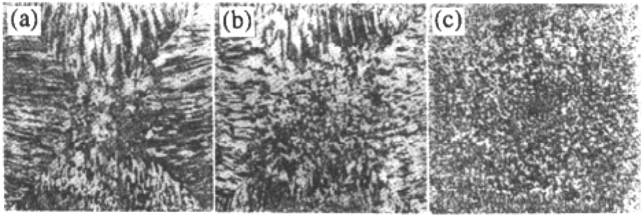
Fig. 3 Experimental results of columnar-to-equiaxed transition (a) T p =1823K, (b) T p =1798K, (c) T p =1773K

Fig. 4 Plots of 3D dendrite profiles and central cross sections from calculations (a) 3D dendrite profiles, (b) central cross sections, (c) part of central cross sections, (d) single central cross section
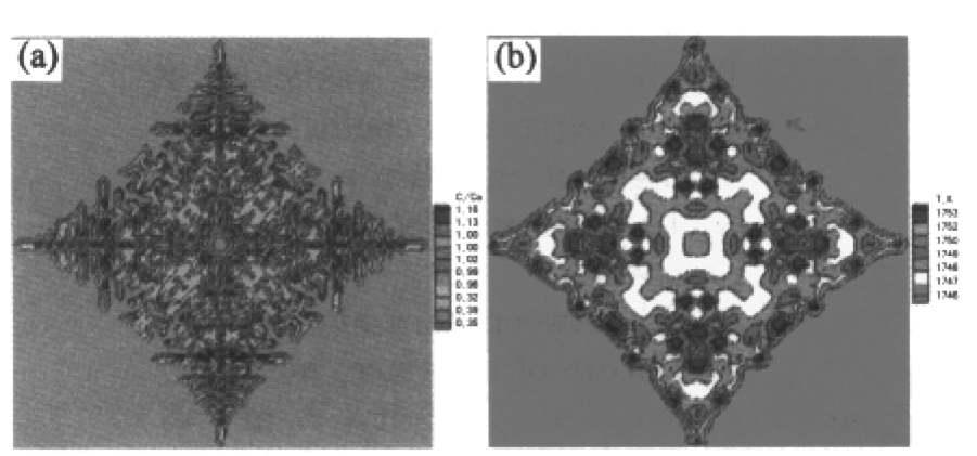
Fig. 5 Plots of the concentration and temperature field profiles at central cross section from calculations (a) concentration field, (b) temperature field
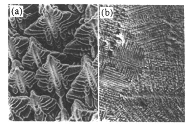
Fig. 6 Photographs of typical dendrite pattern taken by Glicksman (a) 3D dendrite growth, (b) dendrite pattern at a cross section
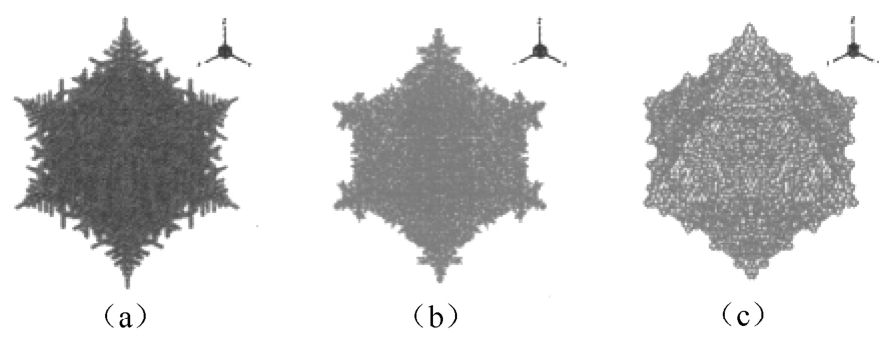
Fig. 7 Three-dimensional morphology of free dendrite with different γ i (a) γ i =0.04, (b) γ i =0.03, (c) γ i =0.02
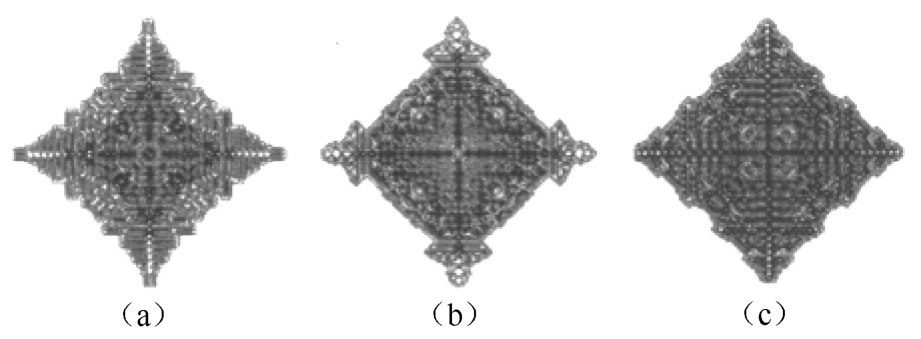
Fig. 8 Two-dimensional dendrite profiles at the central cross section with different γ i (a) γ i =0.04, (b) γ i =0.03, (c) γ i =0.02
The dendrite profiles shown in Fig. 4 also indicated that some small molten pools, in which the solute content is higher when k <1, exists in the interdendritic areas. Their existence is one of main reasons resulting in the formation of micro defects such as microsegregation and microporosity. So microstructure related defects could be predicted based on the calculated dendritic growth and final microstructure patterns and further the basic of their formation could be understood by numerical simulation.
A mathematical model for the three-dimensional simulation of free dendritic growth and microstructure evolution was developed based on the growth physics of crystal grains and basic transfer equations such as heat, mass and momentum transfer equations. Many factors including constitutional undercooling, curvature undercooling and anisotropy, which had vital influences on the microstructure evolution, were considered in the model. Simulated results show that final microstructural patterns and free dendritic growth could be predicted reasonably and calculated results were coincident with experimental results. The simulated results of free dendritic growth indicate that the strength of anisotropy has significant effects on free dendritic growth, dendrite profile, micro solute distribution and micro temperature distribution. The tree-like grain profiles with fully-grown parallel secondary dendritic arm clusters tend to be formed at the intensive anisotropy. Near octahedral grain profiles with small protuberances of surface tend to be obtained at low strength of anisotropy. The existence of small molten pools in the interdendritic areas could be predicted based on simulated results of free dendritic growth. This is helpful to understand the fundamental of the formation of microstructure related defects such as microsegregation and microporosity. Future work will involve:(1) a more thorough model validation through measurements of dendrite profile, temperature and solute distribution, (2) an investigation on influences of other parameters on dendrite profiles, (3) a complete consideration of segregation of multielements.
The work was sponsored by the Significant Project of National Natural Science Foundation of China (No. 59990470—3), the National Significant Fundamental Research Project of the Ministry of Science and Technology of China (No. G2000067208—3) and the Fundamental Research Project of Tsinghua University.
[1]M. C. Flemings and R. W. Cahn: Acta Mater ,2000, 48 ,371.
[2]M. E. Glicksman, E. Winsa, R. C. Hahn, et al : Metall. Trans. ,1987, 19A ,1945.
[3]M. A. Chopra, M. E. Glicksman and N. B. Singh: Metall. Trans. ,1988, 19A ,3087.
[4]L. Nastac: Acta Mater. ,1999, 47 (17)4253.
[5]Baicheng LIU: J . Mater. Sci. Technol .,1995, 11 ,313.
[6]Xu QY, Feng WM, Liu BC, et al : Acta Metall. Sin. ,2002, 38 ,799. (in Chinese)
[7]Q. Y. Xu and B. C. Liu: Mater. Trans. ,2001, 42 ,2316.
[8]Z. J. Liang, Q. Y. Xu, J. T. Li, et al : Rare Metal. Mat. Eng. ,2002, 31 ,353.
[9]W. Oldfield: ASM Trans. ,1966, 59 ,945.
[10]C. A. Gandin, C. Charbon and M. Rappaz: ISIJ Inters .,1995, 35 ,651.
c Specific heat, J. kg -1 ·K -1
C Species mass fraction,%
C L Species mass fraction in liquid,%
C S Species mass fraction in solid,%
C 0 Initial species mass fraction,%
D L Species diffusion coefficient in liquid, m 2 ·s -1
D S Species diffusion coefficient in solid, m 2 ·s -1
f L Mass fraction of liquid
f S Mass fraction of solid
g x , g y , g z Component of gravity acceleration, m·s -2
G Grain size, m
i L Coordinate figure of interfacial liquid cell
i S Coordinate figure of interfacial solid cell
J Interfacial tension, J·m -2
K Permeability, m 2
k Equilibrium partition ratio
k B Boltzmann constant
L Latent heat, J·kg -1
m L Liquidus slope, K/%
n max Maximum density of grain, m -3
N Density of grain, m -3
p Pressure, Pa
P G Capture probability
T S Solidus temperature, K
t Time, s
u x , u y , u z Component of velocity, m·s -1
V n Interface moving velocity, m·s -1
x , y , z Coordinates, m
β T Thermal expansion coefficient, K -1
β C Solutal expansion coefficient
γ i Strength of anisotropy
Γ Gibbs-Thomson coefficient, m·K
ε Emissivity
θ i Angle between normal and i axis
κ Curvature of interface, m -1
λ Thermal conductivity, W·m -1 ·K -1
λ i Dimension of symmetry
μ Kinetic viscosity, Pa·s
ρ Density, kg/m 3
Δ G Total free energy change, J
Δ G V Volume free energy change, J
Δ G J Interfacial free energy change, J
Δ t Time step, s
Δ T Undercooling, K
Δ T c Constitutional undercooling, K
Δ T k Kinctic undercooling, K
P L Interfacial liquid cell
P S Interfacial solid cell
S Area, m 2
T Temperature, K
T L Liquidus temperature, K
T P Pouring temperature, K
T R Environmental temperature, K
Δ T N Centre of distribution, K
Δ T r Curvature undercooling, K
Δ T t Thermal undercooling, K
Δ T σ Standard deviation of distribution, K
Δ x ,Δ y ,Δ z Mesh size, m
Superscript * Solid/liquid interface
Subscript ref Reference