


Key words : Directional solidification, Ni-based superlloy, Turbine blade, Numerical modeling.
Abstract : A mathematical model for three-dimensional simulation of directional solidification process of single crystal turbine blade of Ni-based superalloy investment castings was developed based on CA-FD method. Complex heat radiation among the multiple blade castings and the furnace wall were considered in the model. Temperature, grain growth interface and structure defects of single blade sample casting of single crystal and multiple turbine blade castings were investigated respectively. The experiments were carried out to validate the modeling results. It can be seen that the simulated results of microstructure evolution and structure defects were predicted reasonably and coincident with experimental. It is indicated that three-dimensional solidification simulation technique is a powerful tool for understanding the fundamental of directional solidification process and the formation of structure defects in directionally solidified and single crystal blade castings and finally for optimizing the product and process design as well.
Ni-based superalloy turbine blade castings with columnar grain (DS) and single crystal (SX) produced by Bridgman directional solidification technology have been used in advanced gas turbine for aeronautic and energy industry as well. Since the last two decades of last century, great efforts have been done to study directional solidification technology. Original researches [1] were focused on one or two dimensional model without the consideration of radial temperature distribution to simulate the directional solidification process. K. O. Yu [2] studied the directional solidification process through commercial FEM software and developed the defects map which represented the correlation between the thermal gradient and casting defects. A two-dimensional model was developed by Saitou and Hirata [3] to analyze the shape of liquid-solid interface in Bridgman directional solidification. Compared with experimental results, Galantucci [4] investigated the directional solidification process of turbine blades through 2D FEM method. With the consideration of heat conduction and radiation, Wang and Overfelt [5] presented a new two-dimensional model which could solve the variational radiation view factor with the withdrawal process. J. R. Li [6] investigated the solidification process of single crystal investment castings by ProCast, a commercial software. From 1990s, microstructure simulation of castings became new research hot topics, many approaches have been presented for the computational modeling of microstructure evolution, such as deterministic, probabilistic models and phase field method, but few of them were used to study the single crystal solidification. Cellular automata (CA), dynamic systems in which space and time are discrete, was originally developed by Hesselbarth and Gobel [7] in recrystallization and applied first by Rappaz and Gandin [8] to the simulation of grain structure formation in solidifica tion processes. Based on CA method, Xu [9] developed shape functions to describe the approximate contour of dendrite grain. Kermanpur and Rappaz [10] developed a CA-FE model and investigated the microstructure evolution of turbine blade produced by LMC method. On the assumption of given undercooling and nucleation parameters, Wang and Lee [11] analyzed the correlation of primary dendrite arm spacing and technical parameters of superalloy castings by CA-FE model without consideration of real turbine blade shape. Carter and Gandin [12] developed a process model for grain selection during the solidification of single crystal investment castings and study the geometrical factors influencing competitive growth and the efficacy of two designs of grain selector. Liang [13] investigated the directional solidification process and microstructure evolution of superalloy by CA-FD model.
In this paper, a stochastic modeling based on CA-FD method was studied for simulating the evolution of multiple superalloy turbine blades castings. Complex heat transfer between blades and furnace wall in the directional solidification of multiple turbine blades was considered in this model. The simulation results of solidification process, solidification interface and structure defects of turbine blade castings were compared with experimental results respectively.
1.All the thermophysical properties are constant.
2.The temperature of heating and cooling zones is constant respectively.
3.Radiation exchanges in an enclosure composed of diffuse-gray surfaces.
4.The influence of melt convection is neglected.
5.The grain growth is controlled by thermal diffusion instead of solute diffusion.
The transient non-linear heat conduction equation is as follows:

Where T represents temperature; t is time; c is specific heat; L is latent heat; ρ is density; λ is heat conductivity; x , y and z are the coordinates, f S is mass fraction of solid phase, Q net is net energy exchange between body and external environment, Q net is 0 for the interior of the body.
Since only radiative heat transfer occurs between shell mold and furnace wall, it is important to handle the heat radiation boundary condition. According to the law of gray body radiation, the net heat release of a diffuse-gray surface can be calculated as follows:

Where, q out , i is outgoing radiation energy flux of surface i , q in , i is radiation energy being received, A i represents the surface area.
The incoming radiation energy is a combination of the outgoing radiant energy from all the surfaces being visible to surface i . The view factor φ i-j is the ratio of radiant energy leaving from surface j to surface i to all the radiant energy leaving surface j . Thus:

Where, N is the sum of the surfaces which are visible to surface i . Then the net heat release of surface i can be expressed:

Although the theory of the net radiation energy can be derived easily, it is hard to deal with the view factor φ i-j . For multiple blades heat radiation exists between shell and shell, between shell and furnace wall and also between the different blades. This will make the calculation of φ i-j more complicated.
In this paper, a numerical method derived from Monte Carlo method [14] was adopted to deal with the heat radiation between every two discrete surfaces. Fig. 1 is a 2D schematics for the calculation of heat radiation between a cell and its visible shell cells or furnace wall. The radiation energy from a cell to the outside is divided averagely by a number of rays distributed uniformly in a semicircle (half sphere for 3D). The reaching end of each ray will be recorded, which maybe is the shell surface cell in the same or different blade, or the furnace wall. Then the temperature of the end of ray will be memorized to calculate the heat radiation along this ray.

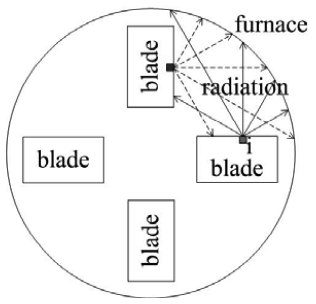
Fig. 1 Schematics for the calculation of heat radiation
where, σ is Stefan-Boltzman constant, ε is emissivity, n is the number of rays, T i and T j are temperature. Because the position of the shell surface relative to the furnace wall is changing in the withdrawal process, φ i-j is not constant and changes in every time step. However, for the shell surface and its adjacent visible parts, φ i-j is constant.
For a 3D finite difference surface cell I , there is 1 to 5 surface (s) involved into heat radiation, each of which can transfer heat by radiation with other visual surface cells. So the cell heat exchange by radiation can be expressed:

A continuous nucleation model was employed to calculate the nucleus density in the undercooled melts[8]:

where, N max is the maximum nucleus density,Δ T σ is the standard deviation of the distribution,Δ T N is the average nucleation undercooling, f S (Δ T ′)is the fraction of solid phase.
The growth model is based on the CA method. The detail of the CA method can be referred to references[9, 13].
The Ni-based superalloy was used for experiments.
Before multiple blade castings experiment, single simplified SX blade sample casting was cast through Bridgman process in the laboratory at withdrawal rates of 270mm/h and 420mm/h respectively in order to validate the numerical model of microstructure evolution. The 3D sketch of single SX blade casting is shown in Fig. 2.Both temperature measurement and microstructure observation were carried out to validate the simulation results.
The schematic of Bridgman process for multiple blade casting is shown in Fig. 3.Before casting, the ceramic shell mold with an open bottom of multiple DS/SX turbine blades was fixed on water-cooled copper chill and heated to a specified temperature. After pouring, the copper chill and the ceramic mold were withdrawn at a predetermined rate, v , from the heating zone to the cooling zone. The upper portion of mold above the baffle remained hot while the lower part of mold below it was cooled by water cooling unit and radiation.
Multiple DS and SX blades, placed on the chill plate with circular distribution, were cast at the rate of 200mm/h. There were 4 thermocouples placed on the surface of one of multiple blades for each case, as shown in Fig. 4, to record the temperatures. In DS blade, points 1 and 3 were at outboard side of blade with circular distribution, far from the center of the furnace, while points 2 and 4 were close to the center. In SX blade, points 3 was at outboard side and point 4 was at inboard side, points 1 and 2 were placed along the center line of the blade surface at different height.
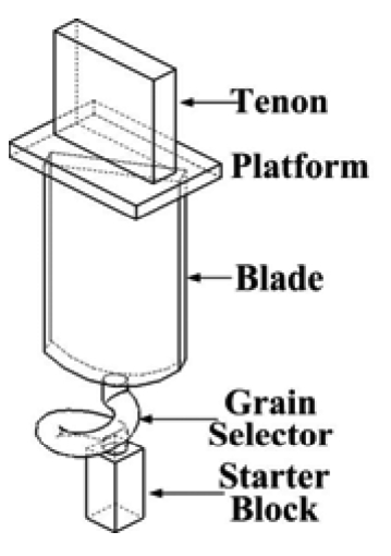
Fig. 2 3D sketch of single SX blade sample casting
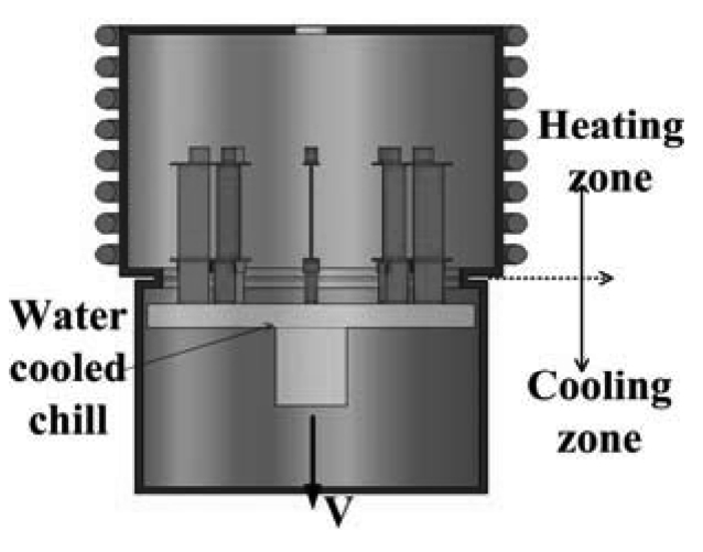
Fig. 3 Directional solidification process of multiple turbine blade castings
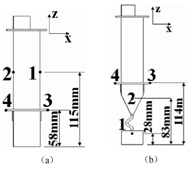
Fig. 4 Sketch of thermocouple positions in the multiple blade castings (a) DS model (b) SX model
The simulated temperature distribution of single simplified SX blade sample casting was validated by the experimental results and agreed well. The crystal growth interface of single SX blade castings at different withdrawal rates is shown in Fig. 5.With the increase of withdrawal rate the curvature of solidification front increased gradually. When the withdrawal rate stepped from 270mm/h up to 420mm/h, remarkably concave growth interface appeared. When the whole solidification fraction went up to about 60%, the solidification front reached the bottom of the platform. Then, the nucleation of new grains occurred at the corners of platform of turbine blade casting at withdrawal rates of 420mm/h as shown in Fig. 5(d). During the following stage of solidification, newly nucleated grains grew up and finally formed structure defects such as high angle boundaries (HAB). Experimental results of final microstructure in the platform are shown in Fig. 6.It can be seen that high angle boundaries were not found in turbine blade casting at the withdrawal rate of 270mm/h, as shown in Fig. 6(a), while they existed in turbine blade casting at 420mm/h as shown in Fig. 6(b).
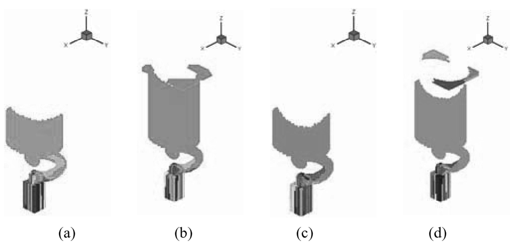
Fig. 5 Simulated microstructure evolution of single SX blade casting (a) and (b) v =270mm/h, (c) and (d) v =420mm/h (a) and (c) solidification fraction:40%, (b) and (d) solidification fraction:60%
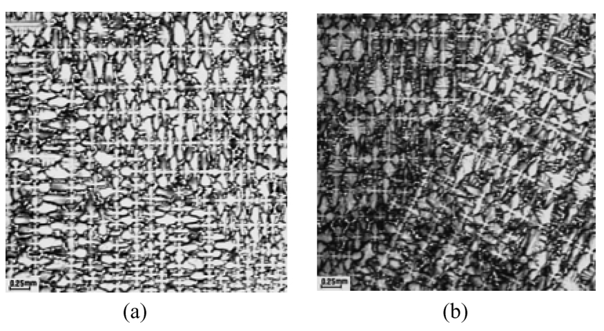
Fig. 6 Final microstructure in the platform of single SX blade castingat different withdrawal rates. (a) v =270mm/h, no HAB(b) v =420mm/h, HAB observed
Cooling Curves. Fig. 7 shows the comparison between the experimental and calculated cooling curves of multiple DS blade castings at four positions. From Fig. 7, it can be seen that the calculated cooling curves agree well with the experimental ones. In the DS blade casting, the body of blade is symmetrical. Points 1 and 2 are at the same height and the points 3 and 4 as well. For the circular distribution of multiple blade castings, points 1 and 3 are close to the heater of the furnace and there exists great heat radiation between outside of the blade and the heater, while points 2 and 4 are in the inside of the circle and face other blades and the chill plate. As the blades were withdrawn with chill plate from heating zone to cooling zone, more radiation heat can loose from outside of the blades than the inside. As a result, the unsymmetrical heat boundary causes the great temperature difference between the different positions along the horizontal positions, as shown in Fig. 7(b).
Fig. 8 shows the comparison between the experimental and calculated cooling curves of multiple SX blade castings at four positions. For SX blade point 3 is located at the outside, while point 4 inside. Great temperature difference occurs between point 3 and 4 because of the same reason as DS blade. From the cooling curves it can be seen that the simulated results are very close with the experimental ones.
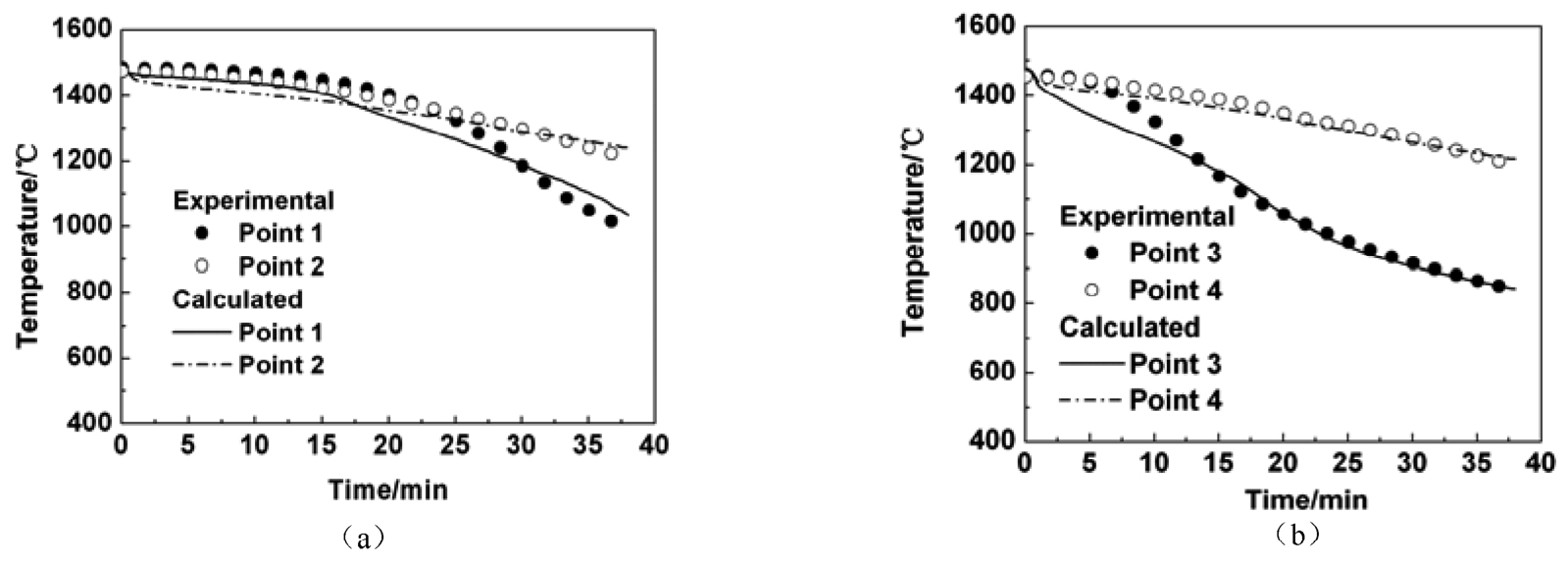
Fig. 7 Comparisons between calculated and measured cooling curves of multiple DS blade castings (a) Points 1 and 2 (b) Points 3 and 4
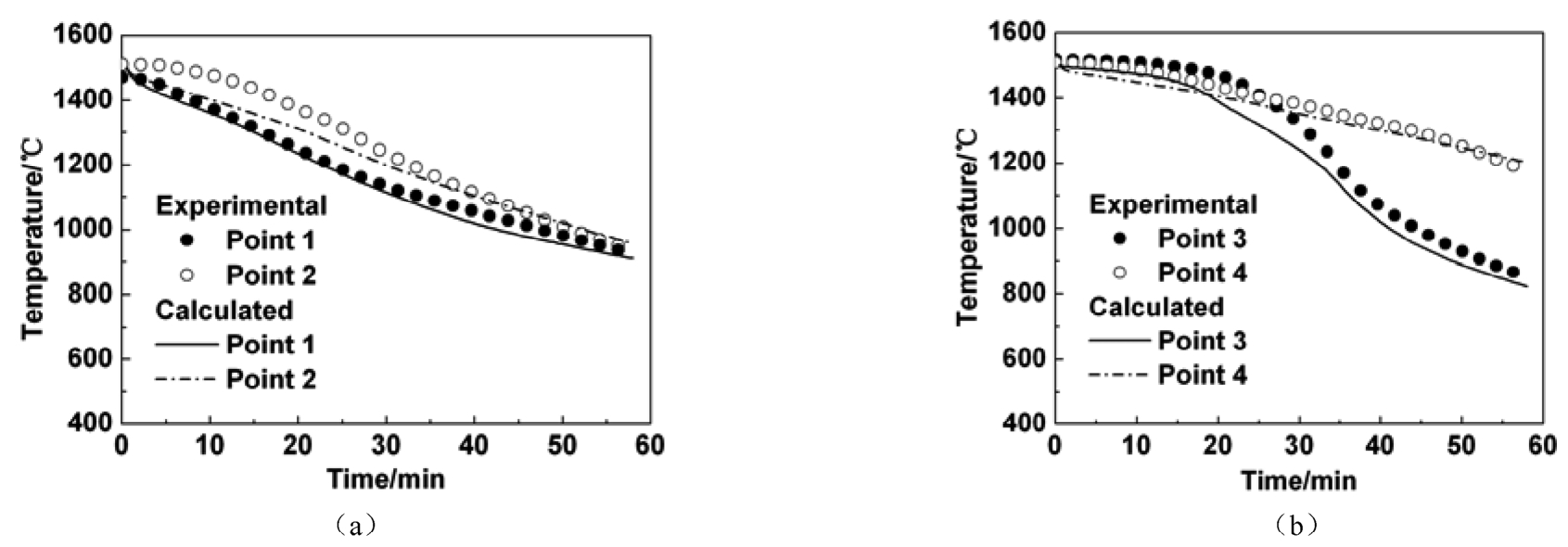
Fig. 8 Comparisons between calculated and measured cooling curves of multiple SX blade castings (a) Points 1 and 2 (b) Points 3 and 4
Temperature Distribution. Fig. 9 shows the temperature distribution of multiple DS blade castings in the solidification at the withdrawal rate of 200mm/h. It can be seen that the isothermal lines are not horizontal. The temperature of the outside of the blade is lower than that of the inside due to the interaction among the multiple blades. On the solidification interface, the outboard temperature is still lower than that of the inboard side.
Fig. 10 shows the temperature distribution of multi ple SX blade castings in solidification process at the withdrawal rate of 200mm/h. Similar with the DS model the solid/liquid interface is uneven. The outside of the interface is higher than the inside, and the outside temperature in front of the interface is lower than the inside, which agrees well with the experimental cooling curves.
Growth Interface. The simulated and experimental results of microstructure of the multiple DS blade castings are shown in Fig. 11.In the root of the blade, the grains grow upward directionally. Where there is abrupt change of blade section, the isothermal lines become uneven, which may lead to the new grains formation in the corner. During the growth process, the growth interface remains uneven. Fig. 11(d) is the microstructure of a real DS blade casting from the experiment. It can be seen that the prediction result of microstructure is similar to that of the experimental result.
Fig. 12 shows the simulated results of grain growth of the multiple SX blade castings at the withdrawal rate 200mm/h. It can be seen that after only one grain grew upward out of the grain selector, new nucleation could form at the corner of the abrupt change of the blade section. Further experiments of microstructure evolution are in process.
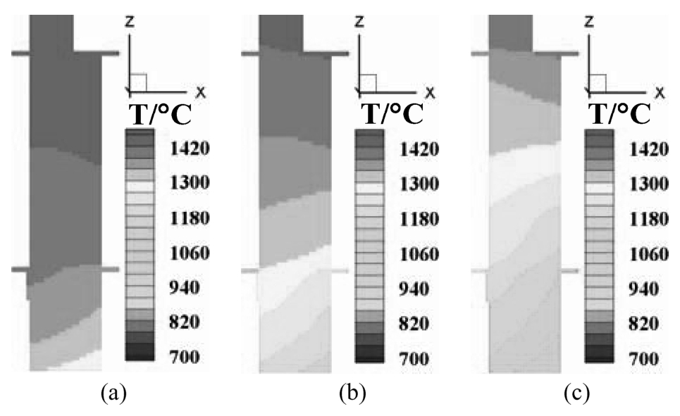
Fig. 9 Temperature distribution of multiple DS blade castings at different solidification time (a) 10min (b) 20min (c) 30min
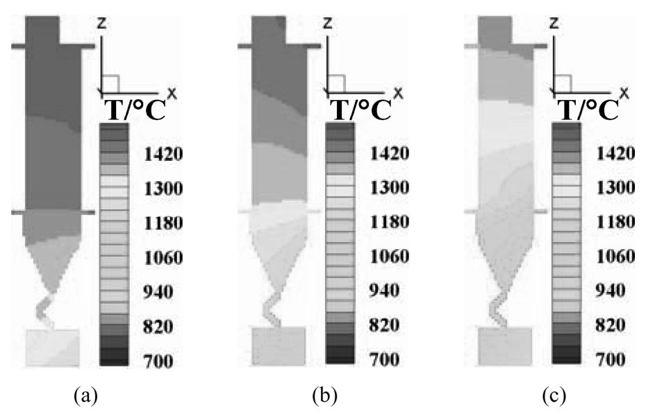
Fig. 10 Temperature distribution of multiple SX blades at different solidification time (a) 15min (b) 30min (c) 45min
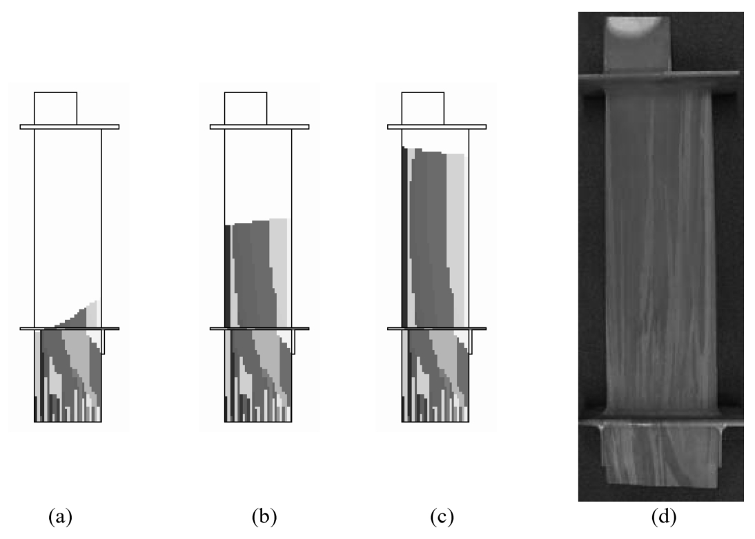
Fig. 11 Microstructure of multiple DS blade castings (a), (b), (c) simulated results at different solidification time, (d) experimental result (a)10min (b)20min (c)30min
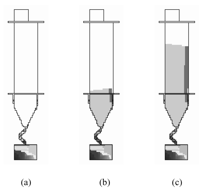
Fig. 12 Microstructure evolution of multiple SX blade castings at different solidification time (a) 15min (b) 30min (c) 45min
Therefore, the simulated results of temperature distribution and microstructure evolution are helpful to optimize process parameters and to improve the turbine blade casting quality.
A mathematical model for 3D simulation of directional solidification and microstructure evolution of superalloy turbine blade castings was developed based on CA-FD method considering complex radiative heat transfer boundary condition. The numerical simulation has been carried out for the directional solidification process of single SX blade sample casting and multiple turbine blade castings respectively. The calculated cooling curves have been compared with the experimental ones and agreed well. The simulation results of microstructure evolution of single SX blade sample casting and multiple DS blade castings were validated by experimental results.
The research is financially supported by National Basic Research Program of China (No. 2005CB724105), NSF of China (No. 10477010) and IHI Research Funds.
[1]R. J. Naumann, "An Analytical Approach to Thermal Modeling of Bridgman-type Crystal Growth, " J . Cryst. Growth. ,58 (1982),554-568.
[2]K. O. Yu, "Solidification Modeling of Complex-Shaped Single Crystal Turbine Airfoils" (Paper presented at the Proceedings of the 7 th International Symposium on Superalloys,Champion,PA,U. S. A.,20 September 1992),135.
[3]Masatoshi Saitou, and Akira Hirata, "Numerical Calculation of Two-Dimensional Unsteady Solidification Problem, " J . Cryst. Growth. ,113 (1991),147-156.
[4]L. M. Galantucci, "A Computer-Aided Approach for the Simulation of the Directional-Solidification Process for Gas Turbine Blades, " J . Mater. Process. Tech. ,77(1998),160-165.
[5]D. Wang et al., "Computer Heat Transfer Model for Directionally Solidified Castings" (Paper presented at the Proceedings of the Conference on Computational Modeling of Materials,Minerals and Metals Processing,San Diego,U. S. A.,23 September 2001),461.
[6]Jiarong Li, and Shizhong Liu, "Solidification Simulation of Investment Castings Single Crystal Hollow Turbine Blade, " J . Mater. Sci. Technol. ,19 (6) (2003),532-534.
[7]H. W. Hesselbarth and I. R. Gobel, "Simulation of Recrystallization by Cellular Automata, " Acta Metall. ,39 (1991),2135-2143.
[8]M. Rappaz, "Probabilistic Modelling of Microstructure Formation in Solidification Processes, " Acta Metall. Mater. ,41(2) (1993),345-360.
[9]Q. Y. Xu, W. M. Feng and B. C. Liu, "A Coupled Macro-Micro Simulation for Prediction of Microstructure of Al Alloy Castings" (Paper presented at the Proceedings of the 10 th International Conference on Modeling of Casting,Welding and Advanced Solidification Processes,Destin,U. S. A.,25 May 2003),149.
[10]Kermanpur. A, and Rappaz. M, "Thermal and Grain-Structure Simulation in a Land-Based Turbine Blade Directionally Solidified With the Liquid Metal Cooling Process, " Metal. Mater. Trans. B ,31 (6) (2000),1293-1304.
[11]P. D. Lee et al., "A Model of Solidification Microstructures in Nickel-Based Superalloys: Predicting Primary Dendrite Spacing Selection, " Acta Mater. ,51 (2003),2971-2987.
[12]P. Carter et al., "Process Modeling of Grain Selection During the Solidification of Single Crystal Superalloy Castings, " Mat. Sci. Eng. A280 (2000),233-246.
[13]Z. J. Liang, "Numerical Simulation of Solidification Process and Microstructure Formation of Investment Castings of Superalloy" (Ph. D. thesis,Tsinghua University,2003).
[14]Robert Siegel, John R. Howell, Thermal Radiation Heat Transfer ,3 rd Edition (U. S. A.:Braun-Brumfield,Inc. 1992).