
下载掌阅APP,畅读海量书库
立即打开


The development of the aviation , energy and automobile industries requires an advanced integrated product/process R&D systems which could optimize the product and the process design as well. Integrated computational materials engineering ( ICME ) is a promising approach to fulfill this requirement and make the product and process development efficient , econonic , and environmentally friendly. Advances in multi-scale modeling of solidification and casting processes , including mathematical models as well as engineering applications are presented in the paper. Dendrite morphology of magnesium and aluminum alloy of solidification process by using phase field and cellular automaton methods , mathematical models of segregation of large steel ingot , and microstructure models of unidirectionally solidified turbine blade casting are studied and discussed. In addition , some engineering case studies , including microstructure simulation of aluminum casting for automobile industry , segregation of large steel ingot for energy industry , and microstructure simulation of unidirectionally solidified turbine blade castings for aviation industry are discussed.
Materials processing technologies play an important role for the manufacturing industry, for example, aluminum and magnesium alloy castings for the automobile industry, superalloy unidirectionally solidified turbine blade castings for the aviation industry, etc. On the other hand, modeling and simulation can play a significant role in guaranteeing the quality of these castings, to shorten the R&D time and to decrease the R&D cost. Recently, multi-scale modeling including macro-and micro-modeling has become a hot topic in computational materials engineering. Hence, macro -and micro-modeling of solidification and casting processes have been extensively studied in our research group, and some advances in macro -and micro-simulation of magnesium and aluminum alloy castings, macrosegregation of large steel ingots, and superalloy directionally solidified turbine blade casting are reported in the paper.
Recently, numerical simulation for microstructural evolution by phase field method has become increasingly popular because of its advantages in morphology description—the dendritic morphology plays a key role in the final performance of cast Mg alloy components. The phase field method is based on Ginzburg-Landau theory, and reffects the influence of diffusion, ordering potential and thermodynamic driving force by using the differential equations. However, most previous research focused on metals with facecentered cubic (f.c.c.) structure, such as Al, Cu and Ni, while metals with hexagonal-close-packed (hcp) structure, such as Mg and Zn, were rarely referred to. Experimental results indicate that the dendritic morphology of metals with hcp structure is totally different from that with f.c.c.structure because of the different crystal lattice. [1-7]
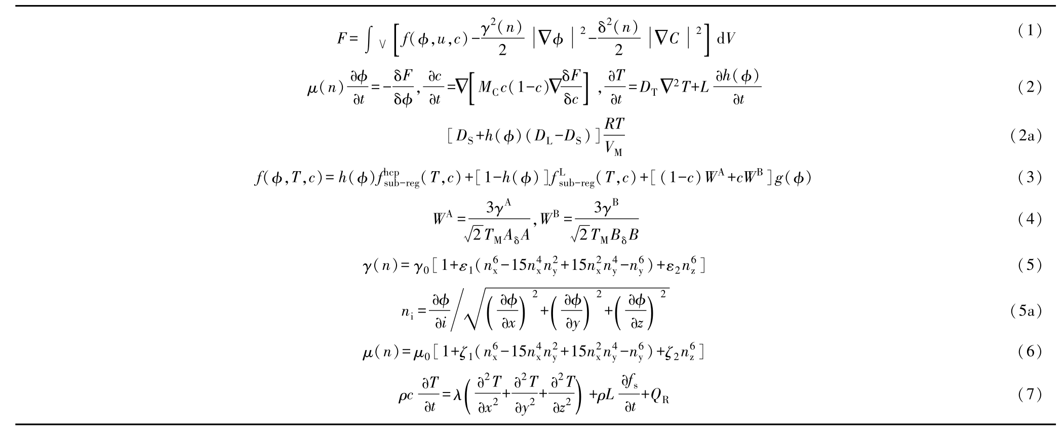
The total free energy of the twophase system is described by a phenomenological Ginsburg-Landau modelas Equation 1, where F is the total free energy of the system, f (φ,u,c) is the free energy density function, φis the phase field variable parameter ranging from negative one in the liquid to positive one in the solid, u and c are the temperature and concentration, respectively, and γ(n) and δ(n) are the gradient energy and concentration field coefficient, respectively. (All equations can be found in the table) The governing equations based on thermodynamic theory for the phase-field coupled with temperature field and solute field can then be expressed as Equation 2.In this equation, μ(n) is the kinetic coefficient, M C is a concentration mobility parameter and is set as shown in Equation 2a. In this equation, h (φ) is the solid fraction given by ϕ 2 (3-2ϕ), D T is the thermal diffusion coefficient, L is the latent heat.
The free energy density function of the system consists of the free energy of the bulk phases and an imposed parabolic potential which is given and can be written as Equation 3,where g(ϕ)-f 2 (1-ϕ) 2 ,and W A and W B are the height of the parabolic potential which will be determined as Equation 4.
An anisotropic function of interfacial free energy and mobility, which reflects underlying crystalline characteristics of the hexagonal close packed lattice, is proposed, as shown in Equations 5 and 6, where n i is unit vector and is given as shown in Equation 5a and i represents x, y, z, respectively, g 0 and m 0 are, respectively, the mean values of interface free energy and kinetic, e 1 , e 2 , and x 1 , x 2 are, respectively, the first-and second-order anisotropic parameters of crystal-melt interface free energy and mobility.
To yield well-developed threedimensional (3-D) dendritic morphologies, phase-field simulations of equiaxed dendritic solidification growth in undercooled melts were carried out. A nucleus was located in undercooled melts and an equiaxed solidification process, governed by both phase-field equation accompanied with associated temperature and solute field equations, was carried out.
Based upon two anisotropic parameters, phase-field calculations yield the entire dendritic solid-liquid interfacial morphologies as shown in Figure 1a, corresponding to the pattern of hexagonal dipyramid. X-ray tomography images based on synchrotron radiation of Figure 1b and the related two-dimensional (2-D) sectional pattern of Figure 1c also supply the proof of the possibility of three-dimensional results.
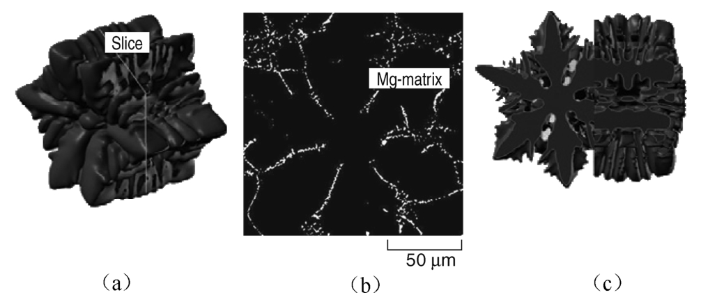
Fig. 1 Simulated result of dendrite morphology of magnesium alloy microstructures (Mg-9wt.% Al). (a) Three-dimensional morphology; (b) synchrotron-radiation-based x-ray tomography slice extracted showing hcp phase patter; (c) related sectional patter results from 3-D simulations.
Mathematical models based on the cellular automaton (CA) method are being used in micro-scale modeling of the dendrite growth, which can quantitatively reproduce most of the dendritic features with affordable computational costs. Böttger and Eiken et al. [8] simulated the dendrite morphology of Mg alloy using phase field (PF) method in two and three dimensions (2-D and 3-D). Huo et al. [9] simulated the 2-D and 3-D as-cast microstructure of AZ91D by using a modified cellular automaton (CA) method, where a prescribed dendrite profile was used instead of physics based simulation considering the solid-liquid interface anisotropy of Mg. Yin et al. [10] simulated the 2-D dendrite morphology of AZ91 Mg alloy using CA-finite element (FE) model under hexagonal mesh.
In this study 2-D and 3-D CA models have been developed to simulate the dendrite morphology evolution of cast Mg alloy and the experiments were caried out for validating the models.
The present CA model employs a scheme based on two sets of mesh. In the 2-D model, a hexagonal mesh is used to perform CA capture procedure to reflect the texture of Mg dendrites, and an orthogonal mesh is used to solve diffusion equations. In the 3-D model, the CA calculation is performed using a mesh defined by the hcp crystal lattice, and the diffusion is solved using a cubic mesh. The growth kinetics of solid-liquid interface is determined based on the difference between the local equilibrium liquid composition and the local actual composition obtained by solving the solute diffusion equation. [11] The solid-liquid interface curvature and growth anisotropy are also considered in the present model. Details of the model can be found in the literature. [12,13]
The simulated morphology of equiaxed and columnar dendrites of AZ91D Mg alloy is shown in Figures 2 and 3.It can be seen that the present model reproduces the Mg dendrites pretty well and provides details about texture, solute segregation, and growth anisotropy and competition.
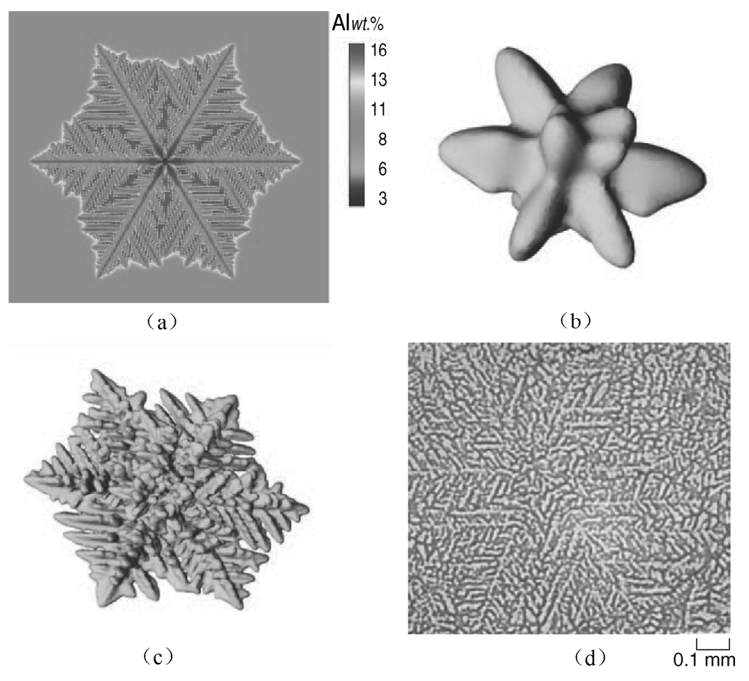
Fig. 2 (a,b,c) Simulated and (d) experimental results of Mg alloy dendrites. (a) simulated 2-D equiaxed dendrite; (b) simulated 3-D equiaxed dendrite at early stage; (c) fully developed 3-D equiaxed dendrite; (d) metallographic results showing texture of Mg alloy dendrites.
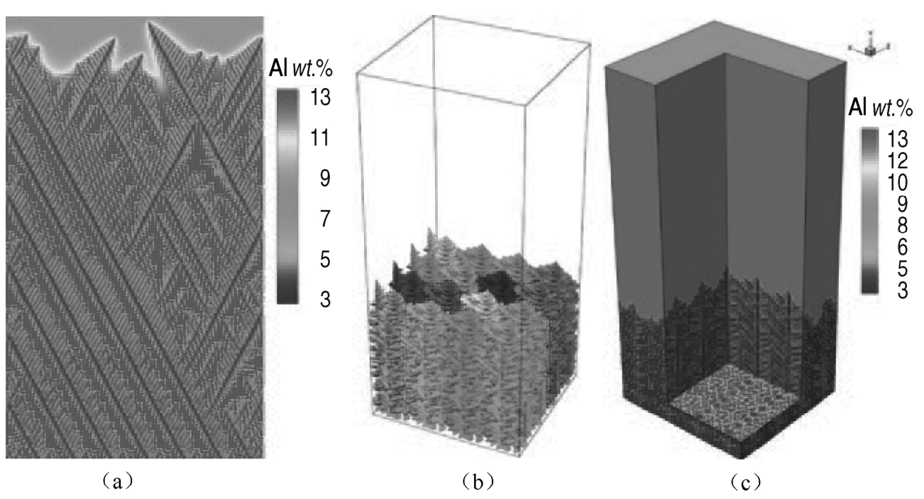
Fig. 3 Simulated columnar dendrite growth of Mg alloy in 2-D and 3-D. (a) columnar dendrites in 2-D; (b) columnar dendrites in 3-D; (c) section view showing the solute field at X-Y, Y-Z, and X-Z planes.
Equations
Besides dendrite morphology, the microstructure evolution of Al 7wt.%Si alloy was also studied by MCA method. [14] A step-shaped sample casting to verify the model and then an engineering case study were carried out. The comparison between the simulated and experimental microstructure from specimens at different position s (20、40 and 60mm in thickness) of the step-shaped sample casting is shown in Figure 4.As shown in Figure 4, grain size and secondary dendrite arm space become smaller when the step thickness decreases.
For an engineering case study, a modified CA model coupled with finite difference method was used to simulate the microstructure evolution of an aircraft turbine wheel casting of Al-7wt.%Si alloy. The casting shape and the position of the specimens are schematically shown in Figure 5, and the thinnest part of the casting is only 2mm in thickness. Specimens were taken from the longitudinal cross-section of the wheel casting indexed as P1 to P7 in sequence. The comparison between the simulated and experimental microstructure of different specimen is shown in Figure 6.
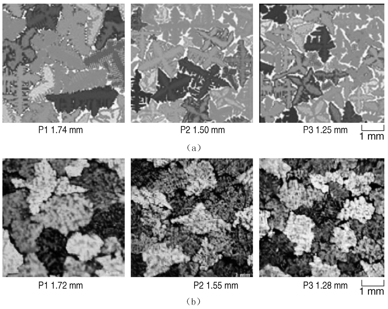
Fig. 4 Comparison of simulated and experimental results of step-shaped casting (grain size). (a) simulated results (b) experimental results.
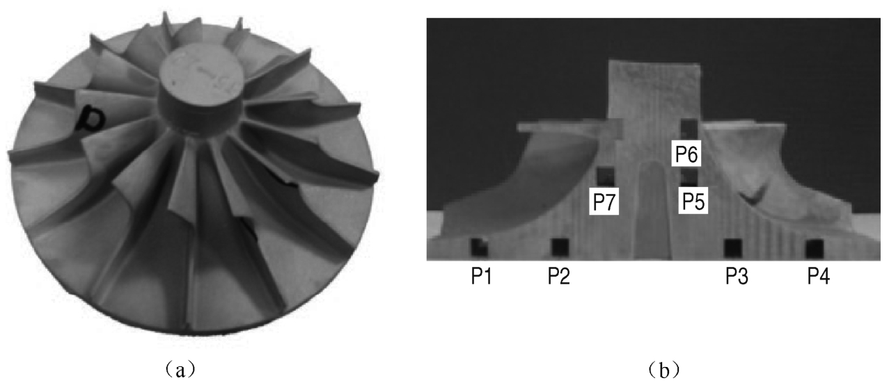
Fig. 5 Schematic of an aircraft turbine wheel casting. (a) aircraft turbine wheel casting; (b) specimen positions.
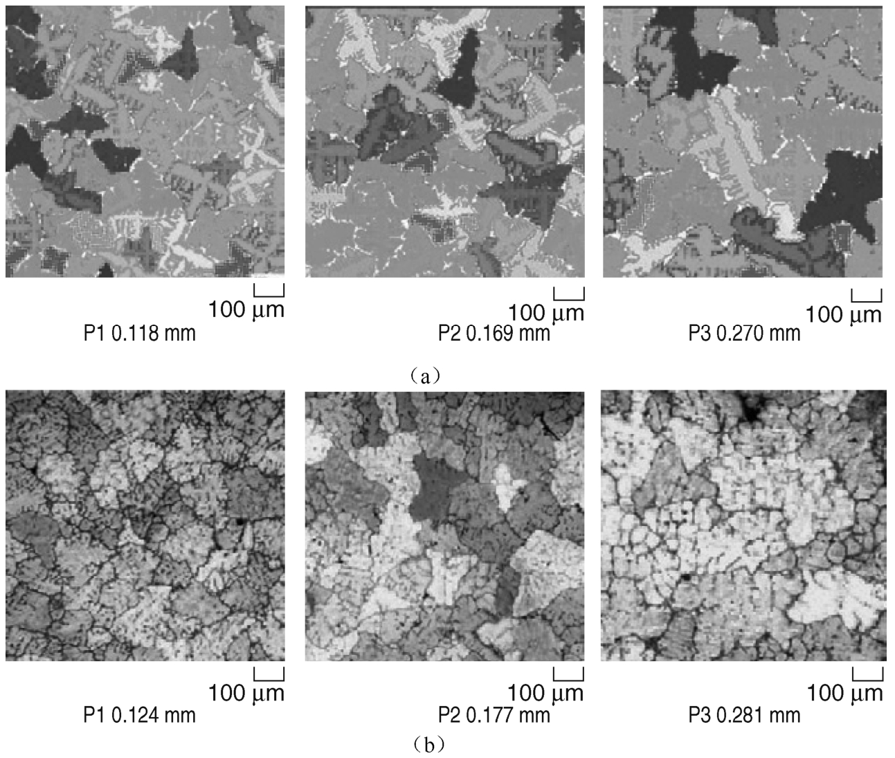
Fig. 6 (a) simulated and (b) experimental microstructure of an aircraft turbine wheel casting (grain size).
Unidirectionally solidified and single crystal Ni-based superalloy turbine blade castings produced by Bridgman directional solidification technology are currently used in both the aeronautic and energy industries as key parts of the gas turbine engines. The final microstructure of the blade casting directly determines the casting mechanical properties. As a powerful tool, numerical simulation technology could be used to study the directional solidification process and optimize the process parameters.
The schematic of the directional solidification process of turbine blade casting is shown in Figure 7.The metal pouring and solidification process take place in the directional solidification furnace under vacuum environment.
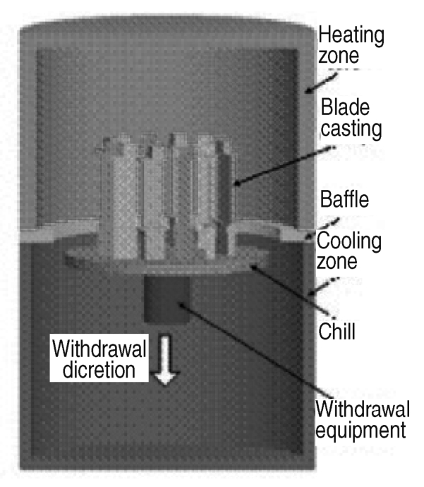
Fig. 7 Schematic of Bridgman directional solidification process.
Complex heat transfer exists during the directional solidification process. The macro-temperature distribution within the casting and shell was calculated according to the transient nonlinear heat transport equation as shown in Equation (7),where T is the temperature, t is the time, ρ is the density, c is the specific heat, L is the latent heat,λ is the heat conductivity; x , y and z are the coordinates; f s is the mass fraction of solid phase; Q R is the heat radiation exchange between the shell surface and the furnace wall.
The huge number of memories required to calculate the view factors for each surface cell against others makes it extremely complicated and difficult for the heat radiation calculation in directional solidification. In this paper, a numerical method derived from the Monte Carlo method was proposed to compute the heat radiation in directional solidification, with much less memory required and a higher accuracy. The details can be seen in Reference[15].
The microstructure simulation was based on the modified CA method. [16] A continuous nucleation mode [17] was employed to calculate the nucleus number in the undercooled. The growth speed of the dendrite tip could be calculated based on the KGT model. [18]
Considering the characteristic of directional solidification, a layer by layer method was proposed to calculate the microstructure formation of a single crystal turbine blade. [19] The mushy zone included several layers in longitudinal direction in macro-scale. We divided every layer into many cells further at microscale. At a macro-time step, the microstructure evolution in the microcomputational domain was calculated. Finally modeling results of all layers were combined together to form that of the whole turbine blade.
Each grain's orientation was randomly determined in this model. Therefore, the grains which were not well-aligned with respect to the maxi-mum gradient of the temperature field would grow at a much slower speed than those which were best aligned, which made them grow behind the growth front. This made it possible for those well-aligned grains to have their secondary and tertiary side arms grow out and occupy the space just in front of the less well-aligned grains. The above process can be used to describe the competitive grain growth in the starter block of grain selector. [20]
In order to investigate the influence of varying withdrawal rates on the casting microstructure, both experiments and simulation of two groups of Ni-based superalloy blade castings with different processing parameters (Group A and B) were carried out. The simulated microstructure evolution of blade casting at different time in group A, with a constant withdrawal rate of 7.0mm/min.is shown in Figure 8.It could be seen that stray grains existed at the edge of the platform of the blade. The simulated microstructure evolution of blade casting at different time in group B, with varying withdrawal rates is shown in Figure 9.It could be seen that no stray grains were found at the platform of the blade casting, and the produced casting was a whole single crystal super lloy blade.
The microstructures in different sections of the whole blade of group A by experiment with a constant withdrawal rate is shown in Figure 10.It could be seen both in the simulated and experimental results that stray grains appeared at the edge of the platform and grew up to the top of the blade. That explains why a high withdrawal rate would not be acceptable to get a complete single crystal blade casting.
The microstructures in different sections of the whole blade of group B by experiment with varying withdrawal rates is shown in Figure 11.No stray grains were found at the edge of the platform both in the simulated and experimental results.
The grain evolution process within the seed selector during solidification at different times is shown in Figure 12.The liquid is not displayed so that the solid-liquid interface could be clearly shown. It is indicated that a great number of tiny equiaxed grains emerged at the bottom surface of the starter block, and transferred into a much smaller number of columnar grains when growing upwards, which is well known as the grain competition process determined by the heat flux direction and the grain's fastest growth direction. The grain number decreased quickly in the starter block, leaving only less than ten columnar grains growing into the spiral. The grains in the spiral continued to decrease when growing upwards, and only one of them survived firom this grain selection, which finally grew into a whole single crystal casting. The measuring experiments from S1 to S7 sections were compared quantitatively with the simulation, which shows a reasonable correspondence. [20]
The production of large steel ingots with improved chemical homogeneity is of great concern for steelmakersto meet stringent requirements for high quality and large integrated forgings typically used for pressure vessels of nuclear power plants. Macrosegregation, as one of the main defects in large steel ingot, refers to chemical inhomogeneity in cast metals at the scale of the product. It cannot be mitigated through the subsequent processing, and hence negatively impacts the properties of final products. [21, 22] The multi-ladle pouring (MP) process, i. e., sequential pouring of liquid steel with different carbon contents, [23-26] has been widely used to suppress macrosegregation in large industrial steel ingots, especially several tons in weight. However, it is very difficult to completely avoid certain carbon segregation in a 360-t steel ingot, despite the MP process as well as other modern technologies of metallurgical production was used. [25]
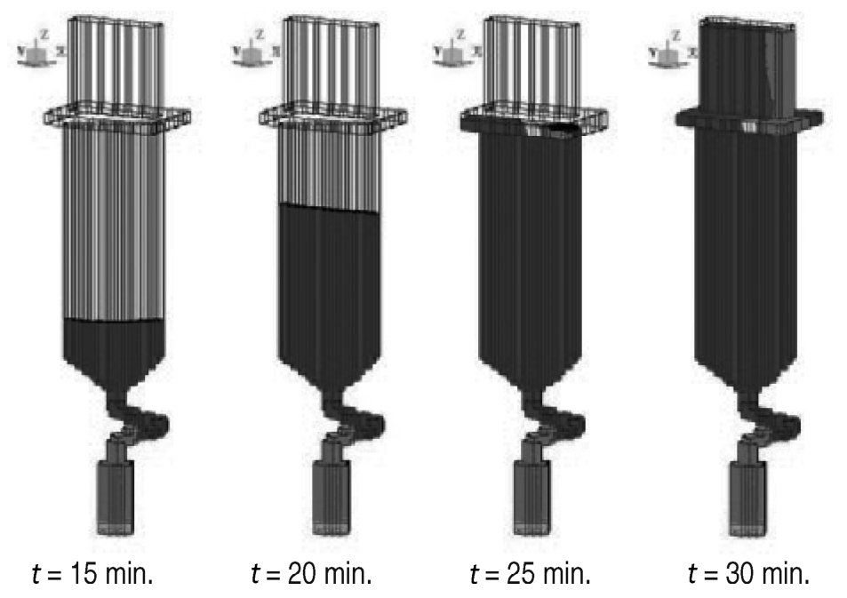
Fig. 8 Simulated microstructure evolution in group A at different time.
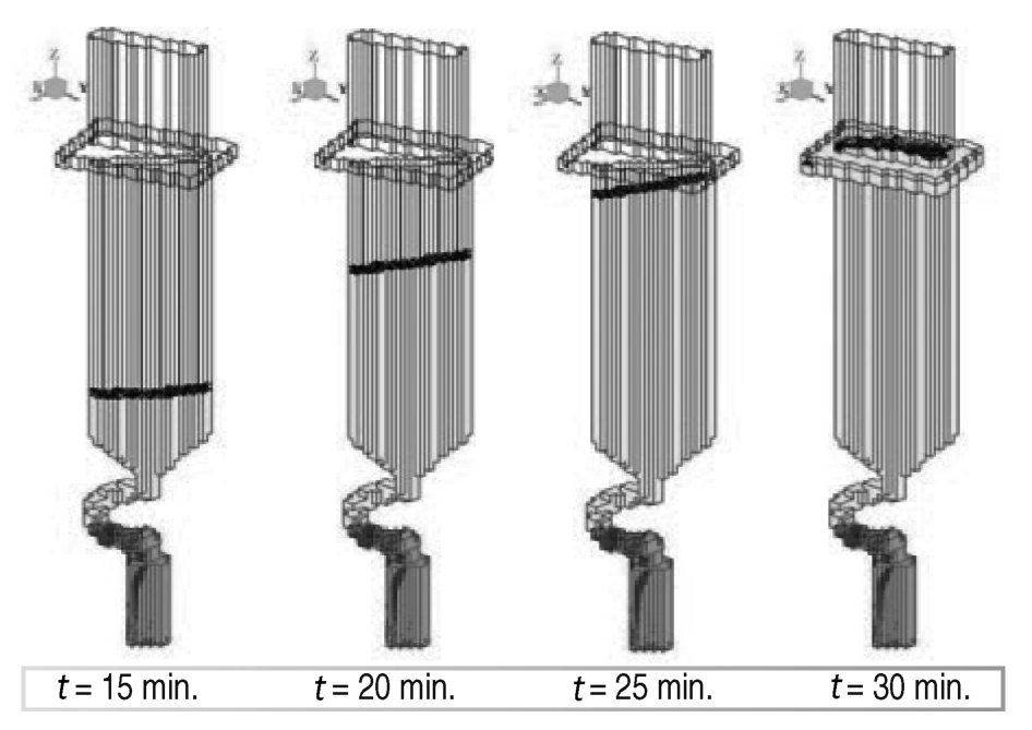
Fig. 9 Simulated microstructure evolution in group B at different time.
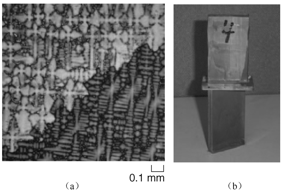
Fig. 10 Experimental microstructures of blade casting in group A with stray grains.
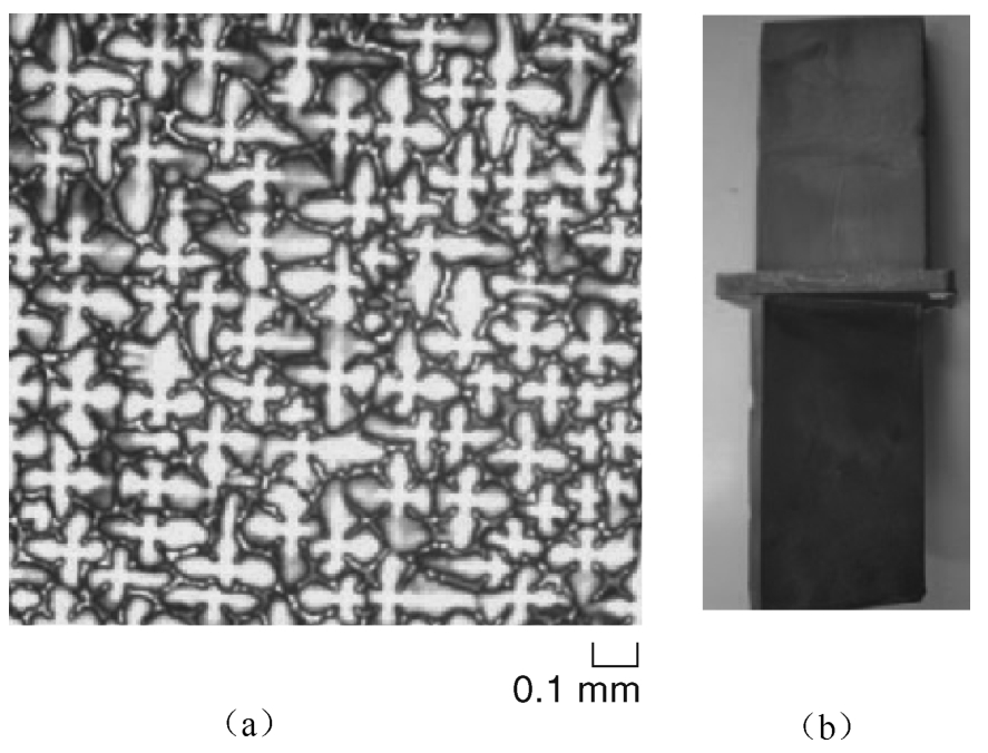
Fig. 11 Experimental microstructures of blade casting in group B without stray grains.
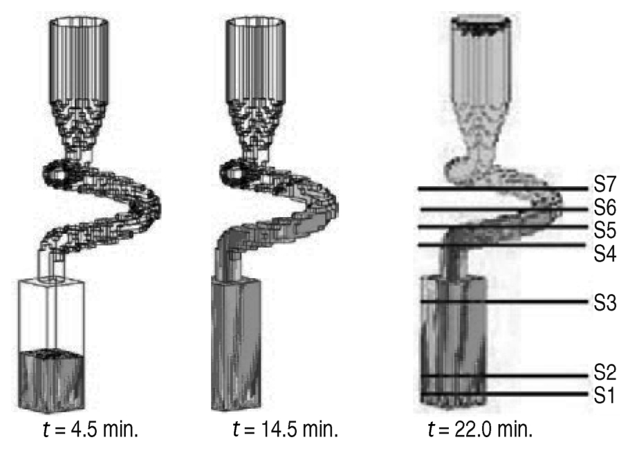
Fig. 12 Simulated grain evolution in the grain selector.
This paper presents some simulated results based on recently developed macrosegregation model. [27] The model was first validated by using a benchmark test, andthen used to simulate the macrosegregation in a 300-t MP steel ingot.
The model is based on the continuum theory, and it involves a fully coupled numerical solution of mass, momentum, energy, and species conservation equations in the liquid, solid, and mushy zones. The thermosolutal convection and the induced macrosegregation in large steel ingots can be numerically simulated by the model. It should be mentioned that multiphase solidification models are available in the literature that take into account melt convection and grain sedimentation (for example,References[28]and [ 29]). The application of these sophisticated models to large industrial ingots, however, is limited due to the large computational resources required to resolve the variety of the phenomena over the process scale.
The validation of the model was performed on the well-known Hebditch-Hunt (HH) benchmark experiment. [30] In this experiment, macrosegregation resulting from the solidification of a Pb-48wt.%Sn alloy in a rectangular cavity was measured. The thermophysical data and parameters used in the calculation were identical to the ones used in Reference [31] an existing benchmark simulation. Figure 13 shows the segregation ratio of tin in the solidifying cavity. It can be observed that the present predictions compare well with the corresponding results in Reference[31].Furthermore, the predicted segregation maps at the end of solidification are generally in good agreement with the experimental results of HH(detailed comparison refers to Reference[27]).
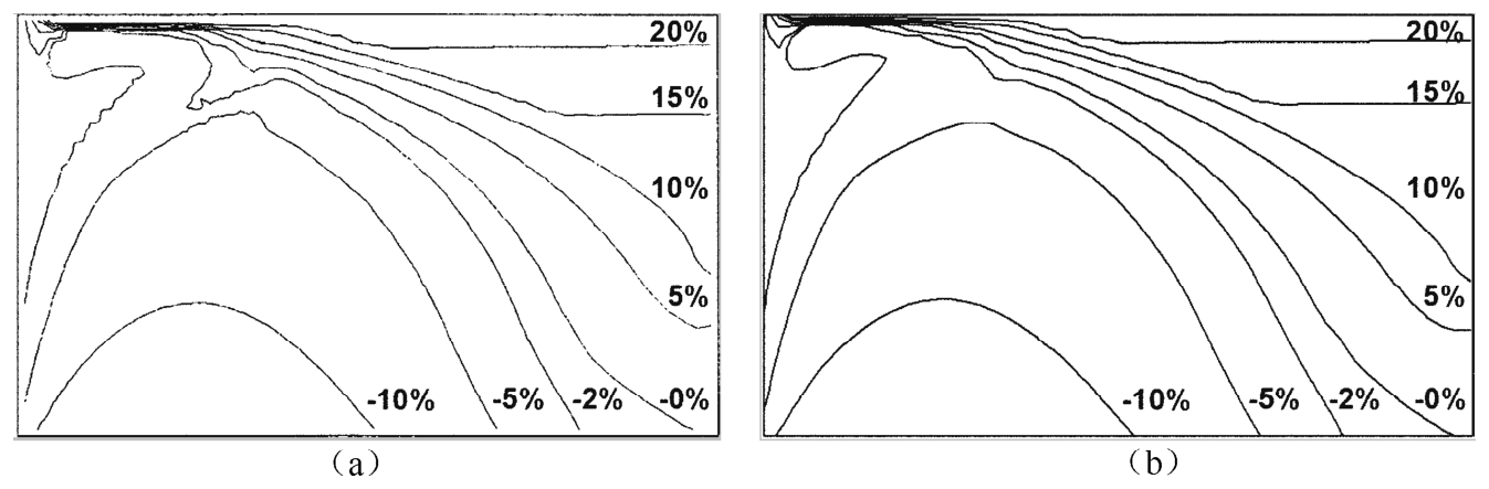
Fig. 13 Macrosegregation map in a solidifying cavity at t=400 s. (a) Existing simulation; (b) present simulation.
The simulation was carried out for a large 300-t steel ingot (Fe-0.36wt.%C) 4.5 m in height and 3.4 m in mean width. Teeming was ignored, and no superheat was considered for the molten steel. The schematic of MP process is shown in the left side of Figure 14, showing that the first ladre contains 150-t molten steel, the second 90-t and the third 60-t, while the final macrosegregation pattern of carbon in the right side of Figure 14.
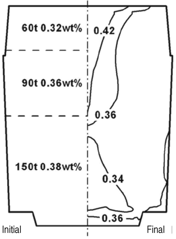
Fig. 14 Schematic of MP (left) and simulated results of final macrosegregation pattern (right) of a 300-t steel ingot.
The classical macrosegregation pattern in a large steel ingot is predicted, including an intense positive segregation in the hot top and a conically shaped negative segregation zone at the bottom of the ingot. It is indicated that certain carbon macrosegregation is not completely avoided in the simulated MP ingot. However, the MP process should have some positive effect on reducing macrosegregation from industrial experience and the sim ulation demonstrates the capability of the model to predict the macrosegregation for large steel ingot in industry. Nonetheless, the flow and mixture behavior of the molten steel from multiple ladles during the teeming process needs to be taken into account for further study.
Phase-field and cellular automaton models for simulating the dendrite morphology of cast Mg alloys have been developed, by incorporating the anisotropic formulae, which provide the insight into both the solid-liquid interfaces patterns and solidification morphologies evolution in hcp based metals or alloys. An MCA model was used to study the microstructure evolution of aluminum alloy casting for engineering application. A mathematical model for macrosegregation pattern of large steel ingot was also studied. Finally, a mathematical model based on CA-FD method was developed for the three dimensional simulation of grain evolution in unidirectional solidification process of superalloy turbine blade casting and the experimental results were studied and compared with the simulated results.
This work is financially supported by National Basic Research Program of China ( Nos.2005CB724105 and 2006CB605208 ), and National Important S & T Program No. 4 ( 2009 ZX04014 ).
[1]L. Gránásy, T. Pusztai, T. Börzsönyi, J. A. Warren, and J. F. Douglas, Nature Mater , 3(2004), pp.645-650.
[2]S.-L. Wang, R. F. Sekerka, A. A. Wheeler, B. T. Murray, S. R. Coriell, R. J. Braun, and G. B. McFadden, Physica D , 69(1993), pp.189-200.
[3]G. Caginalp and W. Xie, Phys , Rev . E , 48(1993), pp.1897-1909.
[4]S. A. David ard T. DebRoy, Science , 257(1992), pp.497-500.
[5]A. Karma, "Prediction of Dendrite Growth Directions" (Presented at the TMS Annual Meeting,San Francisco,CA,2005).
[6]K. Pattersen, O. Lohne, and N. Ryum, Metall . Trans . A , 21(1990), pp.221-230.
[7]F. Czerwinski, Acta Mater ., 50 (2002), pp.3265-3281.
[8]J. Eiken, B. Böttger, and I. Steinbach, Modeling of Casting , Welding and Advanced Solidification Processes-XI (Warrendale,PA: TMS,2006), pp.489-496.
[9]Liang Huo et al., Materials Science Forum , 561-565(2007), pp.1797-1800.
[10]H. B. Yin and S. D. Felicelli, Modeling and Simulation in Materials Science and Engineering ,17(7)(2009),075011.
[11]M. F. Zhu and D. M. Stefanescu, Acta Materialia , 55(2007), pp.1741-1755.
[12]Liang Huo, Zhiqiang Han, and Baicheng Liu, "Twoand Three-dimensional Cellular Automaton Models for Simulating Dendrite Morphology Evolution of Cast Magnesium Alloys" (Presented at the 139th TMS Annual Meeting and Exhibition,Washington State Convention Center,Seattle,14-18 February 2010).
[13]Liang Huo, Zhiqiang Han, ard Baicheng Liu, Materials Science Forum , 638-642(2010), pp.1562-1568.
[14]B. Li, Q. Y. Xu, and B. C. Liu, Materials Science Forum , 561-565(2007), pp.1787-1792.
[15]J. Yu et al., J . Materials Science and Technology , 23(2007), p.47.
[16]M. Rappaz and C. A. Gandin, Acta Metallurgica et Materialia , 41(1993), p.345.
[17]P. Thevoz, J. L. Desbiolles, and M. Rappaz, Metall. Trans. A , 20A(1989), p.311.
[18]W. Kurz, B. Giovanola, and R. Trivedi, Acta Metallurgica , 34(1986), p.823.
[19]J. Yu et al., “Experimental Study and Numerical Simulation of Directionally Solidified Turbine Blade Casting”(Presented at the Asian Foundry Congress,Seoul,Korea,2007).
[20]D. Pan et al, JOM ,62(5)(2010),pp.30-34.
[21]G. Lesoult, Mater. Sci.and Eng . A , 413-414 (2005), pp.19-29.
[22]C. Beckermann, Int. Mater. Rev ., 47(5)(2002), pp.243-261.
[23]M. Tateno, Transactions ISIJ 25(1985),pp.97-108.
[24]H. Ushiyama, G. Yuasa, and T. Yajima, Ironmaking and Steelmaking ,5(1978),pp.121-134.
[25]V. I. Bogdanov, V. A. Durynin, and V. V. Tsukanov, Russian Metallurgy ( Metally )(7)(2007),pp.626-633.
[26]D. R. Liu et al., Int . J . Cast Metais Research , 23(6)(2010), pp.354-363.
[27]W. S. Li, H. F. Shen, and B. C. Liu, Steel Research international ,81(11)(2010),pp.994-1000.
[28]H. Combeau et al., Metall . Mater. Trans. B , 40(2009), pp.289-304.
[29]M. Wu and A. Ludwig. Acta Materialia , 57 (2009), pp.5621-5631.
[30]D. J. Hebditch and J. D. Hunt, Metall. Trans ., 5(1974), pp.1557-1564.
[31]N. Ahmad et al., Metall. Mater. Trans A , 29(1998), pp.617-630.
Baicheng Liu,professor,Tao Jing,professor,Qingyan Xu,associate professor,Houfa Shen,professor,and Zhiqiang Han,associate professor,are with the Department of Mechanical Engineering,Tsinghua University,Beijing 100084,China. Prof. Liu can be reached at liubc@tsinghua.edu.cn.