


The total atomic force of all the atoms between the wire and substrate is F w-s . The micro-scale contact process consists of loading and unloading processes. During the loading process, as shown in Fig. 2-2, F w-s performs attraction with the moving downward of the wire part during the loading process. With the further moving of the wire part, the value of F w-s increases and some atoms of both the wire and substrate come out. At a specific point ( P c point), atomic contact between atoms of the wire and substrate occurs. These specific points for all pairs occur before real contact of the wire and substrate (0 Å distance), and ranked in order of largest to smallest displacement of the wire as Ag-Ag>Cu-Ag>Ag-Au>Cu-Au>Au-Au>Cu-Cu, although the displacement difference is not obvious. Then, due to further moving downward of the wire, the wire and substrate are physically contacted and compressed each other, and for the compressed atoms between the wire and substrate, a repulsive force appears and increases with the displacement of wire in Z -direction. That is, the total attractive force reduces but the total repulsive force increases gradually. At a specific point, F w-s equals 0. The total force equilibrium point ( P e point) is defined as Z -coordinate of wire when F w-s equals 0. P e appears at around 2.0 Å, except for Cu-Ag and Cu-Au pairs. As the further moving downward of the wire, F w-s then shifts to repulsive and increases. As for Cu-Ag and Cu-Au, the plastic deformation appears in the Ag and Au substrates due to the larger hardness of Cu wire, and the total atomic forces (repulsive) are smaller than other four pairs. As the further moving downward of the wire, the repulsive force increases then dramatically decreases after reaching the material's limit of yielding only in Cu-Cu, Ag-Ag, Au-Au, and Ag-Au pairs, and yielding of the wires occurs when the Z -coordinate of wire reach approximately 3.9 Å, 2.8 Å, 3.6 Å, and 3.3 Å, respectively. After yielding occurs, the restructure of lattice starts and plastic deformation occurs.
During the unloading process, with the wire moving along [00-1], F w-s shifts from repulsive to attractive and rapidly increases. When F w-s reaches its valley value, the plastic deformation appears due to the locally strong bonding effects of the atoms between the wire and substrate. F w-s is vibration reducing as the wire moving upward. F w-s of Cu-Cu has the largest valley value of around-55.0 nN among six material pairs, and Cu-Ag has the smallest valley value of-33.0 nN. The heterogeneous bonding pairs have a smaller valley value of F w-s than the homogeneous bonding pairs, except Au-Ag pair.
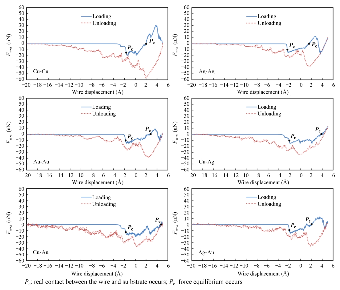
Fig. 2-2 The total atomic force of all the atoms between the wire and substrate as a function of displacement during the loading and unloading processes
Fig. 2-3 shows the dynamic changes of the total energy of all atoms for the six material pairs. The total energy consists of potential energy and kinetic energy. In this work, the temperature is set to avoid the disturbance of kinetic energy. Therefore, the potential energy dominates the total energy.
During the loading process, the total energy first remains unchanged. Then, the total energy decreases because of the reduction of potential energy caused by the approaching of the wire and substrate. As the wire further moving downward, the total energy turns to increase, but only for a short time before second decreasing for Cu-Cu, Ag-Ag, and Au-Ag pairs, but there are no second decreasing for other pairs. The corresponding sharp jumping of the trend indicates wire/substrate materials reaching their yielding points, which leads to a continuous decrease of their potential energies. But for Cu-Ag and Cu-Au pairs, only soft materials (Ag and Au) yield and deform plastically, so that the sharp jumping of the trend is not obvious.
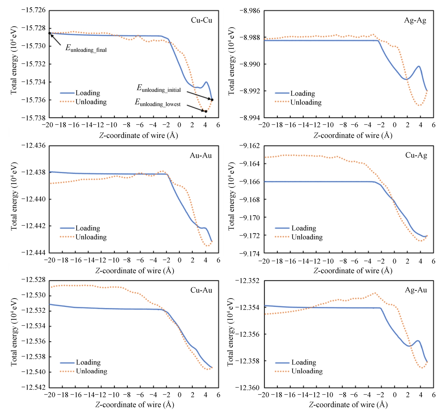
Fig. 2-3 Total energy as a function of displacement during the loading and unloading processes
During the unloading process, the total energy rises rapidly in all material pairs. However, the total energy decreases for Au-Au and Ag-Au pairs after the Z-coordinate of wire reaches-1.0 Å. Since the materials tend to release inner energy autogenic, this characteristic would lead to autogenic breakage of the weld when the weld is tensile over a specific distance.
The larger the range from initial energy ( E unloading_initial ) to the lowest energy ( E unloading_lowest ) in the unloading process, the larger the debonding energy, which implies the bonding strength is larger. From the results, the energy ranges ( E unloading_final ~ E unloading_lowest ) are as follows: Cu-Au (8.271×10 -7 eV)>Cu-Cu (7.424×10 -7 eV)>Cu-Ag (6.056×10 -7 eV)>Au-Au (5.202×10 -7 eV)>Ag-Au (4.204×10 -7 eV)>Ag-Ag (3.747×10 -7 eV).
Fig. 2-4 shows the absolute value of atomic displacement in Z -direction to investigate the local deformation. Colors are assigned to atoms on the (010) slice (the slice is along the A-A′ in Fig. 2-2). Blue color represents atoms with no displacement (0 Å), and red color represents atoms with the largest displacement (1.0 Å or more).
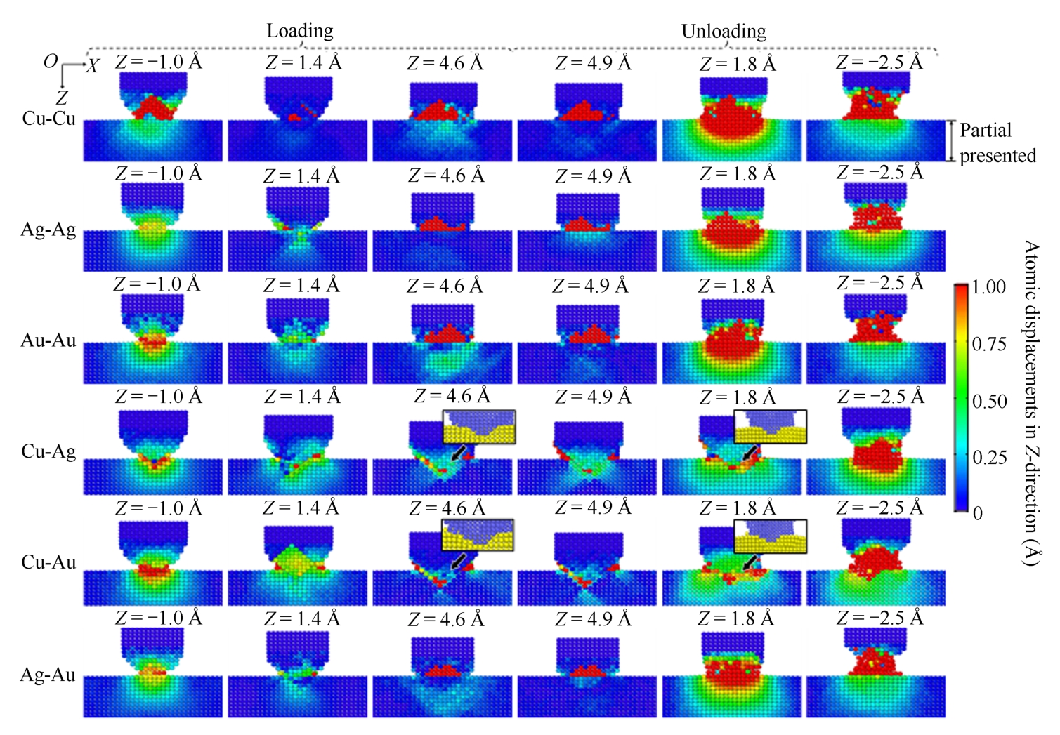
Fig. 2-4 Atomic displacement on the (010) slice of six material pairs during the loading and unloading processes (only presenting a partial area with values over 0 Å)
During the loading process, when the Z -coordinate of wire reaches approximately-1.0 Å, atomic contact between the wire and substrate in six pairs occurs, as shown in the first column of Fig. 2-4(a). Cu-Cu pair has the largest area of red color, and the Ag-Ag has the smallest. For Cu-Cu pair, red color almost only exists in wire. But for Cu-Ag and Cu-Au pairs, most of red atoms exist in substrate due to the larger stiffness of Cu comparing with Ag and Au. Due to further moving downward of the wire, the wire and substrate compress each other. When the Z -coordinate of wire reaches 1.4 Å, as shown in the second column of Fig. 2-4(a), most atomic displacement of atoms decreases, except for Cu-Ag and Cu-Au pairs. It is because that the wire and substrate shift from expanding to shrinking, and atoms are pushed back to their former locations. When the Z -coordinate of wire reaches 4.6 Å, according to Fig. 2-2, yielding has occurred in all material pairs. Moreover, for Cu-Ag and Cu-Au pairs, red color occurs near the interface of the wire and substrate (the interface is shown in partial enlarged figures).
During the unloading process (Fig. 2-4), with the wire moving upward from 4.9 Å to 1.8 Å (the Z -coordinate of wire), the force between the wire and substrate shifts from repulsive to attractive (Fig. 2-2), the wire and substrate tensile each other, so the atomic displacement of the wire and substrate increases in all material pairs. When the Z -coordinate of wire reaches 1.8 Å, as shown in the fifth column of Fig. 2-4, red color occurs in both the wire and substrate, except for Cu-Ag and Cu-Au pairs. For Cu-Ag and Cu-Au pairs, red color occurs near the interface of the wire and substrate (the interface is shown in partial enlarged figures). With further moving upward of the wire, when the Z -coordinate of wire reaches-2.5 Å, as shown in the sixth column of Fig. 2-4, neckbands form between the wire and substrate in all material pairs and their central areas present red color.
Fig. 2-5 shows the equivalent von Mises stress of atoms on the slice of crystal face (010) (the slice is along the A-A′ in Fig. 2-2). The value of von Mises stress, ranging from 0 GPa to 16 GPa, is represented by a color scale from blue to red. Therefore, red color represents the atoms with largest von Mise stress (16 GPa or more), and blue color represents the atoms with smallest von Mise stress (0 GPa).
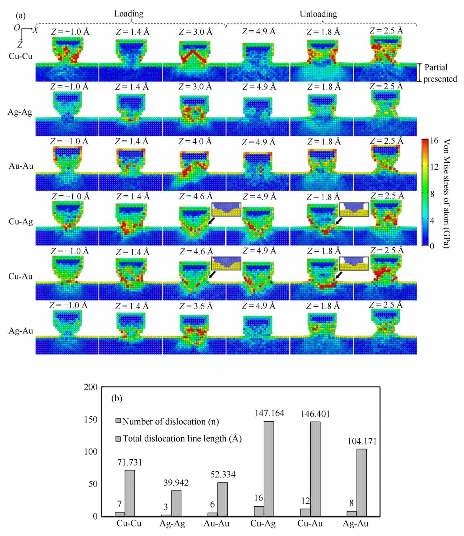
Fig. 2-5 (a) The equivalent von Mises stress of the atoms on an atomic (010) slice of six material pairs during loading and unloading processes (only presenting a partial area with values over 0 GPa); (b) number of dislocation and the length of total shockley partial dislocation line in the third column in Fig. 2-5(a)
During the loading process, when the Z -coordinate of wire reaches approximately-1.0 Å, atomic contact between atoms of the wire and substrate has just recently occurred in six pairs, as shown in the first column of Fig. 2-5(a). Among six pairs, Cu-Cu pair has the largest count of atoms with the largest von Mise stress and Ag-Ag has the smallest. For Cu-Ag and Cu-Au pairs, red color occurs near the interface of the wire and substrate. Then, due to further moving downward of the wire, the wire and substrate compress each other. In Cu-Cu pair, the stress of atoms in the central area of wire decreases, as shown in the second column of Fig. 2-5(a). It is because that the wire and substrate shift from expanding to shrinking, and atoms shift from being attracted to compressed. But in Cu-Ag and Cu-Au pairs, the stress of atoms is still large. After that, as shown in the third column of Fig. 2-5(a), red color occurs almost in wires except for Cu-Ag and Cu-Au pairs. But for Cu-Ag and Cu-Au pairs, red color mainly occurs near the interface of the wire and substrate (the interface is shown in partial enlarged figures), and the profiles of the interface between the wire and substrate present a V-shape curve.
During the unloading process, with the wire moving upward, as shown in the fourth column of Fig. 2-5(a), atomic stress of most atoms decreases except for Cu-Ag and Cu-Au pairs. For Cu-Ag and Cu-Au pairs, atomic stress of most atoms remains constant. When the Z -coordinate of wire reaches approximately 1.8 Å, red color occurs in the central area of the wires except for Cu-Ag and Cu-Au pairs. For Cu-Ag and Cu-Au pairs, red color mainly occurs near the interface of the wire and substrate. After that, as shown in the sixth column of Fig. 2-5(a), neckbands form between the wire and substrate for all pairs, and red color occurs in the central areas of the neckbands. Moreover, during the unloading process, red color mainly occurs in Cu wires for Cu heterogeneous material pairs (like Cu-Ag and Cu-Au).
Fig. 2-5(b) shows the number of dislocation and the length of total Shockley partial dislocation [20] line of six pairs, corresponding to the third column of Fig. 2-5(a). Both of the number of dislocation and the length of total Shockley partial dislocation line could be ranked as Cu-Ag>Cu-Au>Ag-Au>Cu-Cu>Au-Au>Ag-Ag. It shows that heterogeneous material pairs (Cu-Ag, Cu-Au, and Ag-Au) have more dislocations than homogeneous material pairs (Cu-Cu, Au-Au, and Ag-Ag).
According to above discussions, four important displacement points during the loading process are worth attention. Fig. 2-6 shows the atomic displacement on two planes described as A′ABB′ and AA″B″B , which presents the atomic distribution characteristics at these selected displacement points.
(1) Lower boundary of high attractive force interval. According to Fig. 2-2 and Fig. 2-3, it can be found that during the loading process, when F w-s equals around 70% of maximum value of attractive force between the wire and substrate, the atomic contact of the wire and substrate occurs, and the corresponding Z -coordinate of wire is defined as Z LB-HAFI . It also defines the high atomic attractive force interval, which starts from 70% (lower boundary) to 100% of the maximum value of atomic attractive force between wire and substrate.
(2) Displacement equilibrium point. It occurs when atomic displacements of the wire and substrate in the central contact area along the Z -direction equal almost 0 Å during the loading process.
(3) Force equilibrium point. It occurs when F w-s equals 0 N during the loading process.
(4) Starting restructure point. It occurs when the yielding occurs and atoms starts to restructure.
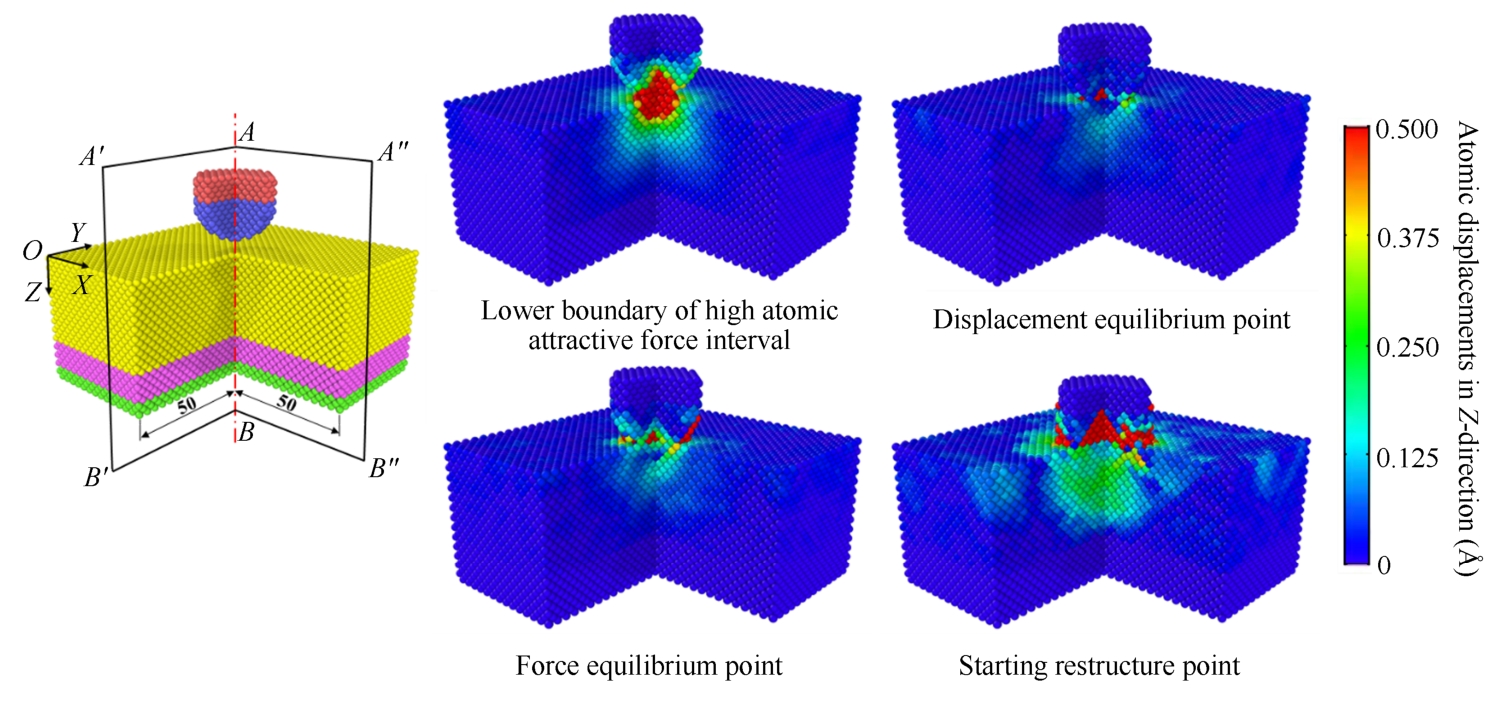
Fig. 2-6 Atomic displacements at 4 displacement points corresponding to the lower boundary of high atomic attractive force interval, displacement equilibrium point, force equilibrium point, and starting restructure point of the Cu-Cu pair, respectively
Fig. 2-7 shows the Z -coordinate of wire corresponding to the lower boundary of high attractive force interval, displacement equilibrium points, force equilibrium points, and starting restructure points of the six material pairs during the loading process.
During the loading process, Z LB-HAFI of Ag-Ag is largest, and Z LB-HAFI of Cu-Cu is the smallest among six pairs. Among homogeneous material pairs (Cu-Cu, Au-Au, and Ag-Ag), the order of Z LB-HAFI value is Ag-Ag<Au-Au<Cu-Cu. Among heterogeneous material pairs, the order of Z LB-HAFI value is Cu-Ag<Ag-Au<Cu-Au. According to the definition of the lower boundary of high attractive force interval, smaller Z LB-HAFI value implies that atomic contact occurs earlier, that is, easier bonding. It also indicates that Ag-Ag bonding would be the easiest and Cu-Cu pair would be the most difficult to be bonded among six material pairs according to Fig. 2-7.
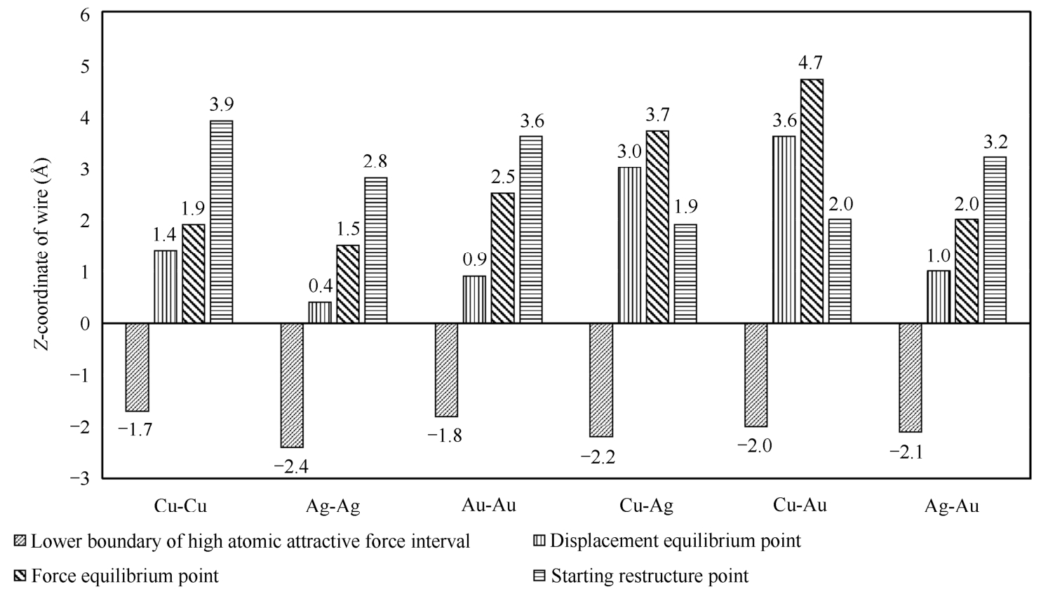
Fig. 2-7 Z -coordinate of wire corresponding to the lower boundary of high atomic attractive force interval (left oblique lines), displacement equilibrium points (vertical lines), force equilibrium points (right oblique lines), and starting restructure points (horizontal lines) of six material pairs
It is also observed that both Cu-Ag (-2.2 Å) and Cu-Au (-2.0 Å) have smaller Z LB-HAFI values than Cu-Cu (-1.7 Å). Moreover, Ag-Au (-2.1 Å) has smaller Z LB-HAFI value than Au-Au (-1.8 Å). It indicates that one material from the homogeneous material pair with small Z LB-HAFI value could be used to form heterogeneous material pairs having improved bonding ability. For example, after replacing Cu in Cu-Cu with Ag, the Z LB-HAFI value of Cu-Cu (-1.7 Å) is reduced to-2.2 Å (the Z LB-HAFI value of Cu-Ag).
For both the displacement equilibrium point and force equilibrium point, two equilibriums occur earliest in Ag-Ag pair and latest in Cu-Au pair among six material pairs. Except for Ag-Au pair, these two equilibriums occur earlier in homogeneous pairs than heterogeneous pairs. For the starting restructure point, in case of homogeneous pairs, the yielding and restructure occur earliest in Ag-Ag pair and latest in Cu-Cu pair among six material pairs (Fig. 2-2). It indicates that in case of Cu-Cu pair, wire has the largest displacement in Z -direction before yielding during the loading process among six material pairs. Moreover, in case of Cu-Ag and Cu-Au pairs, the yielding and restructure occurs before the occurrence of displacement equilibrium and force equilibrium (Fig. 2-2).